

Shunt device of heater
A technology of a shunt device and a heater, applied in the field of dyeing, can solve the problems of increasing nozzle pressure difference, reducing the color difference of the fabric, and being unbalanced, and achieving the effect of reducing the pressure difference and reducing the color difference of the fabric.
Inactive Publication Date: 2011-07-20
WUXI HUIZE GENERAL MACHINERY
View PDF0 Cites 0 Cited by
- Summary
- Abstract
- Description
- Claims
- Application Information
AI Technical Summary
Problems solved by technology
The structure of the existing heater device used for the dyeing machine generally adopts the method of conveying the dye solution in the middle of the pipeline, which will significantly increase the pressure difference between the nozzles, so it is not uniform enough, resulting in reduced color difference of the fabric, longer dyeing time, mixed not enough
Method used
View moreImage
Smart ImageViewing Examples

Examples
Embodiment Construction
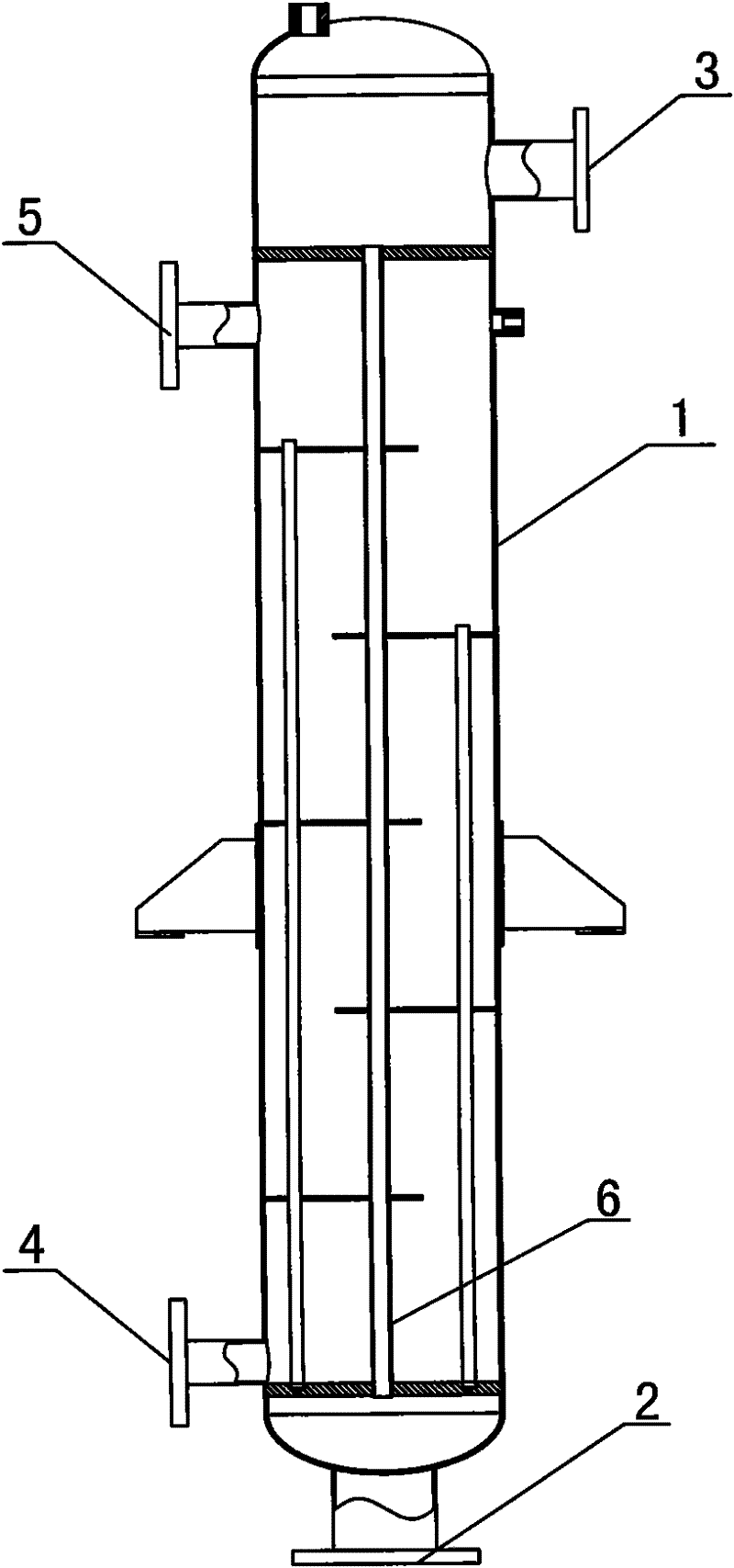
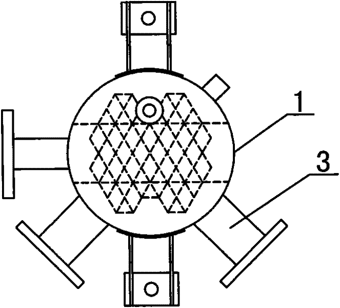
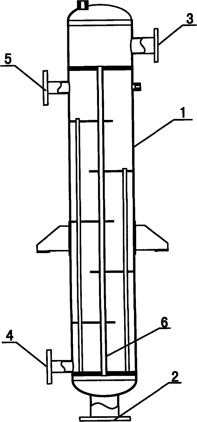
[0012] Such as Figure 1-2 As shown, the heater splitter device of the present invention includes a separate liquid distribution pipeline 6 inside the liquid separation cavity 1, and the dye liquid inlet 2 and the dye liquid inlet 2 are respectively provided at the two ends of the liquid separation cavity 1. Outlet 3, a condensed water outlet 4 is provided on the outside of the cavity located at the dye liquor inlet 2, and a steam inlet 5 is provided on the outside of the cavity located at the dye liquor outlet 3.
Login to View More PUM
 Abstract
The invention relates to a shunt device of a heater, comprising a dispensing cavity. The dispensing cavity is internally provided with a single dispensing pipeline, a dyeing liquor inlet and a dyeing liquor outlet are respectively arranged at both end parts of the outer side of the dispensing cavity, a condensate water outlet is arranged at the outer side of the cavity at the dyeing liquor inlet part, and a steam inlet is arranged at the outer side of the cavity at the dyeing liquor outlet part. The invention has the advantages that a traditional method of shunting dyeing liquor in a pipeline is improved into a method of directly and gradually unifying dyeing liquor to various nozzle systems by a channel through a single pipeline according to a structural principle of uniformly distributing channel air-liquid shunt pressure so as to reduce the pressure difference of various nozzles, further reach the uniform effect and reduce fabric chromatism.
Description
technical field [0001] The invention relates to dyeing technology, in particular to a heater split device. Background technique [0002] Traditional cloth dyeing machines are divided into single type and combined type. In order to adapt to the dyeing of various different types of cloth, it is also possible to purchase multiple dyeing devices with different styles and structural designs. The structure of the existing heater device used for the dyeing machine generally adopts the method of conveying the dye solution in the middle of the pipeline, which will significantly increase the pressure difference between the nozzles, so it is not uniform enough, resulting in reduced color difference of the fabric, longer dyeing time, mixed Not enough. Contents of the invention [0003] In view of the above defects, the purpose of the present invention is to provide a heater split device that can reduce the pressure difference between the nozzles, reduce the color difference of the fa...
Claims
Login to View More Application Information
Patent Timeline
 Patent Type & AuthorityApplications(China)
IPC IPC(8): D06B23/22
Inventor石建明
OwnerWUXI HUIZE GENERAL MACHINERY