Energy pulse output method and device of electric energy meter and electric energy meter

A technology of pulse output and electric energy meter, applied in the field of electric energy meter, can solve the problems of large energy pulse beating value, low instantaneous power signal-to-noise ratio, short step response time, etc.

Active Publication Date: 2011-07-20
HI TREND TECH SHANGHAI
View PDF5 Cites 10 Cited by
  • Summary
  • Abstract
  • Description
  • Claims
  • Application Information

AI Technical Summary

Problems solved by technology

When the current value is relatively small, the I value in formula 2 is relatively small, and the noise remains unchanged, so the signal-to-noise ratio of the current signal is relatively low, and the signal-to-noise ratio of the instantaneous power is correspondingly relatively low, and the filtered instantaneous power also contains There is more noise, therefore, the jump value of the output frequency of the energy pulse is relatively large when the signal is small
However, if a low-pass filter with a greater degree of attenuation to the non-DC low-frequency part is selected, the beating of the small signal can be improved, but the greater the attenuation of the non-DC low-frequency part by LPF1, the longer the step response time of LPF1 , if the step response time of LPF1 is similar to the output pulse interval of energy pulse CF, it will affect the output of energy pulse CF
Due to the small energy pulse output interval when the signal is large, this determines that the step response time of LPF1 should be relatively short. Therefore, in the existing electric energy meter structure, the step response time is usually short but for the non-DC low frequency part. The attenuation is not good enough for the low-pass filter, which leads to the problem that the accuracy of the energy meter fluctuates relatively large when the small signal is input

Method used


Image

  • Energy pulse output method and device of electric energy meter and electric energy meter
  • Energy pulse output method and device of electric energy meter and electric energy meter
  • Energy pulse output method and device of electric energy meter and electric energy meter

Examples


Embodiment 1

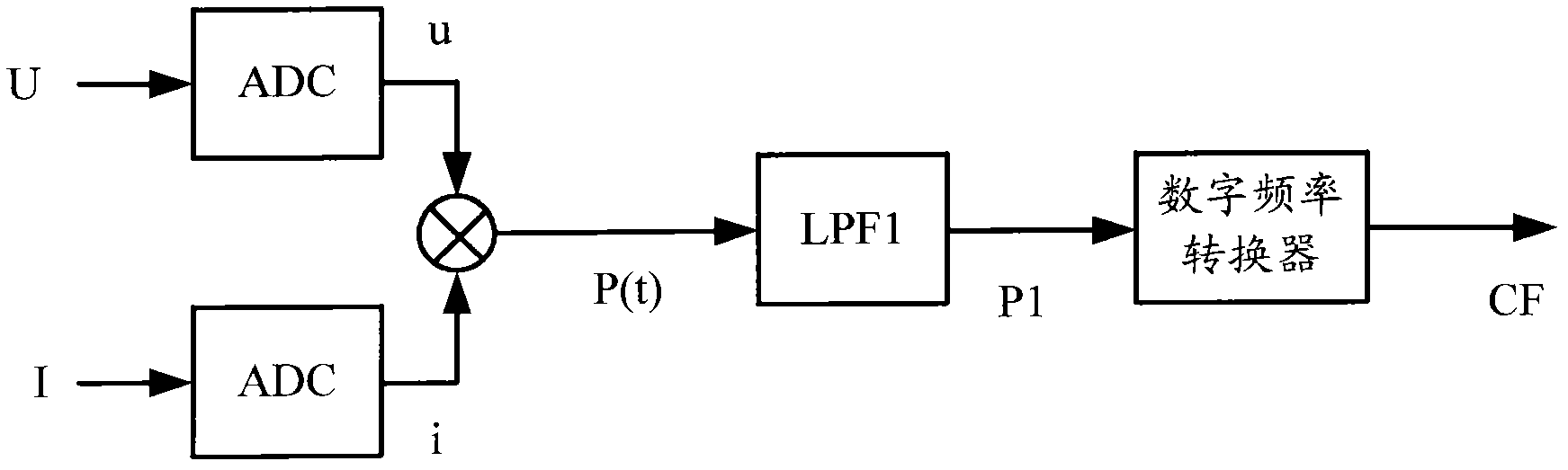
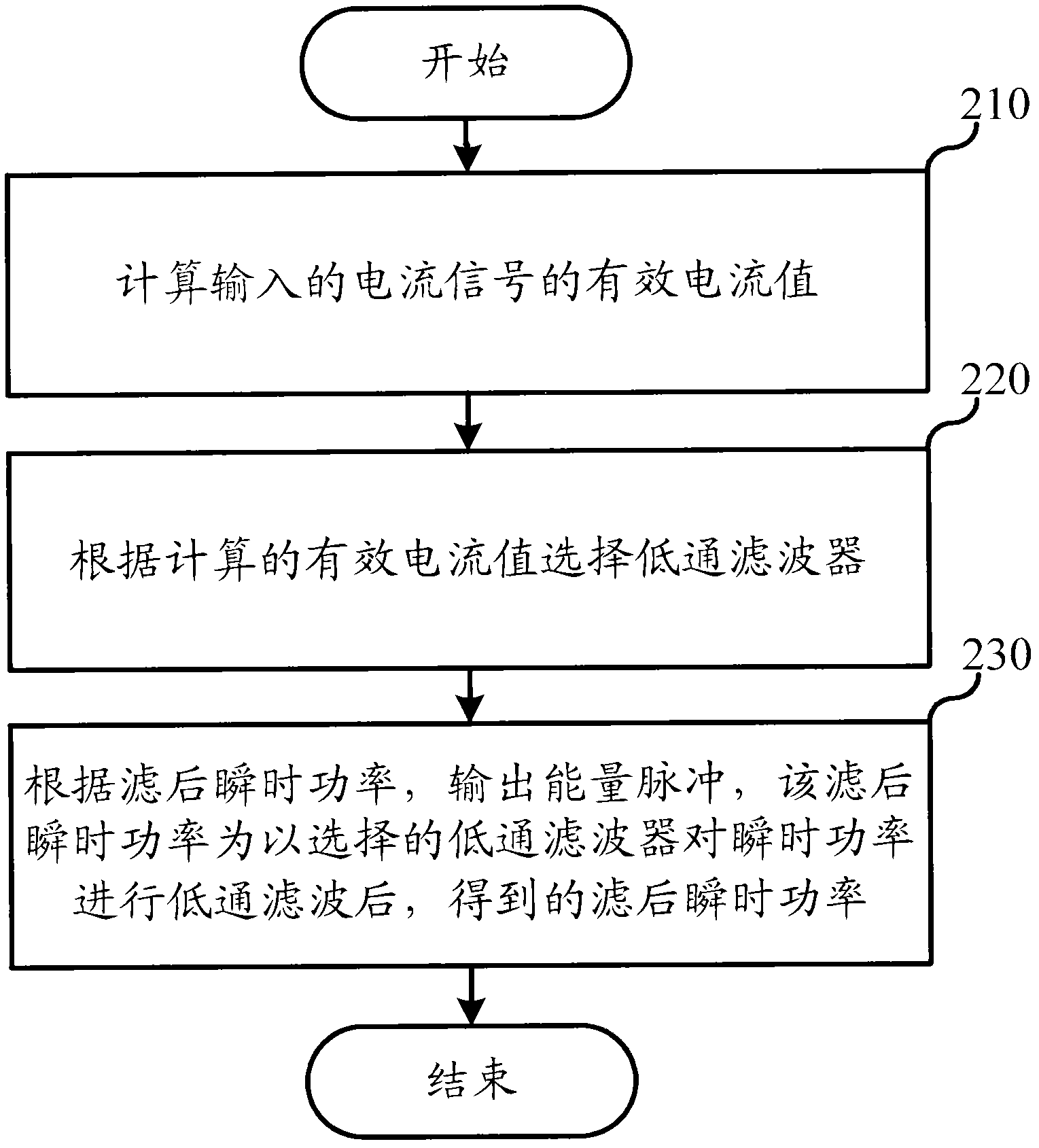
[0040] This embodiment relates to an energy pulse output method of an electric energy meter, and the specific process is as follows figure 2 shown.

[0041] In step 210, the effective current value of the input current signal is calculated. Specifically, in this embodiment, according to the formula: Calculate the effective current value I rms . Among them, N represents the number of periodic sampling points, and i represents the digital signal converted from the input current signal. In addition, those skilled in the art can understand that in practical applications, I can also be calculated according to other formulas that can characterize the magnitude of the input current signal. rms , which will not be repeated here.

[0042] Next, in step 220, a low-pass filter is selected according to the calculated effective current value, and if the calculated effective current value is greater than a preset threshold, a first low-pass filter is selected. If the calculated effe...

Embodiment 2

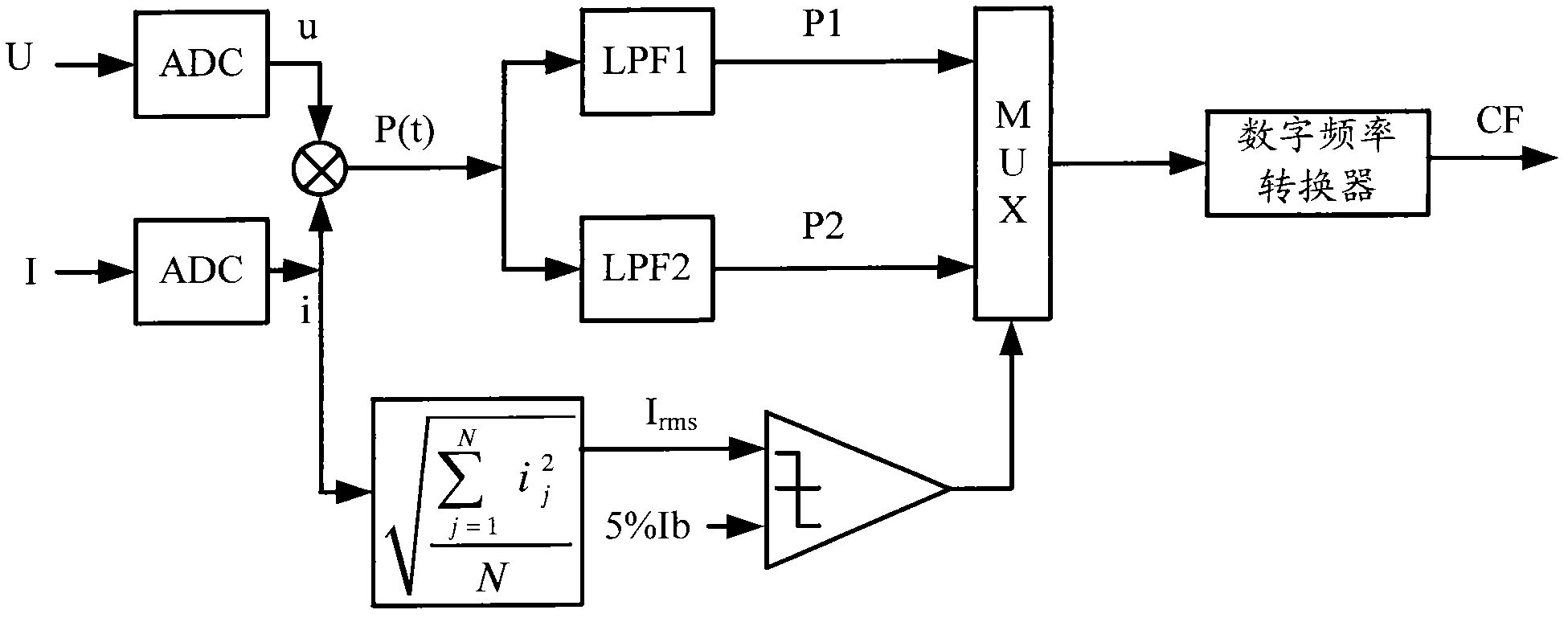
[0051] This embodiment relates to an energy pulse output method of an electric energy meter. The second embodiment is basically the same as the first embodiment, the main difference is that in the first embodiment, the instantaneous power filtered by the selected low-pass filter is used as the effective filtered instantaneous power, and the non-selected instantaneous power is discarded. The instantaneous power filtered by the low-pass filter is obtained to obtain the filtered instantaneous power.

[0052] However, in the second embodiment, the filtered instantaneous power is obtained by enabling the selected low-pass filter and disabling the unselected low-pass filter. The selected low-pass filter, when enabled, low-pass filters the instantaneous power.

[0053] Such as Figure 6 As shown, after multiplying the digital signals u and i of the voltage value and current value to obtain the instantaneous power P(t), according to the comparison result between the calculated effec...

Embodiment 3

[0057] This embodiment relates to an energy pulse output device. Figure 7 It is a structural schematic diagram of the energy pulse output device. The energy pulse output device includes:

[0058] The first low-pass filter and the second low-pass filter are respectively used for low-pass filtering the input signal. Wherein, the step response time of the first low-pass filter is shorter than the step response time of the second low-pass filter, and the attenuation degree of the non-DC low-frequency part of the second low-pass filter is greater than that of the first low-pass filter The degree of attenuation of the non-DC low frequency part.

[0059] The current effective value calculation module is used to calculate the effective current value of the input current signal.

[0060] A selection module, configured to select a low-pass filter for low-pass filtering the instantaneous power according to the effective current value calculated by the current effective value calculat...


PUM


Abstract

The invention relates to the field of electronics and discloses an energy pulse output method and an energy pulse output device of an electric energy meter, and the electric energy meter. Two low-pass filters with different performance are designed. When the effective value of a current is less than or equal to a preset threshold, the low-pass filter which has a longer step response time but has higher attenuation degree to a non-direct current low-frequency part is selected, so that the attenuation to the non-direct current low-frequency part of transient power is better and the energy pulsejitter when a small signal is input is improved. When the effective value of the current is more than the preset threshold, the low-pass filter which has lower attenuation degree to the non-direct current low-frequency part but has a shorter step response time is selected, so that the instantaneity of energy pulse output is not affected.

Description

technical field [0001] The invention relates to the field of electronics, in particular to an electric energy meter in the field of electronics. Background technique [0002] The energy meter samples the analog voltage and current through a Sigma-delta analog-to-digital converter (Σ-ΔADC) and converts them into their digital form, so that the subsequent metering circuit can calculate data such as electric energy, power, and effective value. [0003] The basic structure of the existing electric energy meter is as follows: figure 1 As shown, the voltage value U and the current value I are respectively converted into corresponding digital signals u and i through the Σ-Δ analog-to-digital converter, which respectively represent the digital signals of the voltage value and current value, and the instantaneous power p is obtained after multiplying u and i (t), the instantaneous power passes through a low-pass filter LPF1 to obtain filtered instantaneous power P1, and the filtered...

Claims


Application Information

Patent Timeline
Patent Type & Authority Applications(China)
IPC IPC(8): G01R21/133
Inventor 朱传森萧经华胡建国
Owner HI TREND TECH SHANGHAI
Why Eureka
Try Eureka