Automatic alignment bar shearing top knife component

A knife assembly and tangent technology, which is applied in metal processing and other directions, can solve the problems of not meeting the size accuracy requirements of cutting ribs, offset cutting rib size, vibration of molds, etc.

Inactive Publication Date: 2011-08-03
NANTONG SHANGMING PRECISION MOLD
View PDF0 Cites 1 Cited by
  • Summary
  • Abstract
  • Description
  • Claims
  • Application Information

AI Technical Summary

Problems solved by technology

Because the frame is positioned by the positioning pin 7, when the upper mold and the lower mold are closed, the mold will vibrate, which will cause th

Method used


Image

  • Automatic alignment bar shearing top knife component
  • Automatic alignment bar shearing top knife component
  • Automatic alignment bar shearing top knife component

Examples


Embodiment

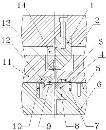
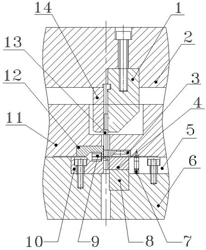
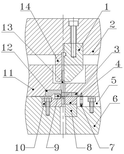
[0010] Such as figure 2 As shown, a kind of automatic aligning and rib-cutting upper knife assembly provided by the present invention includes an upper knife fixing seat 2, an upper knife positioning block 1 is arranged on the upper knife fixing seat 2, and an upper knife 13 for rib cutting is fixed on the upper knife fixing seat 2. On the seat 2, the two sides of the rib cutting upper knife 13 are pressed by the upper knife bead 14, the unloading plate 11 is arranged under the upper knife positioning block 1, and the unloading insert 3 and the unloading block 12 are arranged on the side of the unloading plate 11. At the bottom, a die 4 and a material receiving block 10 are respectively provided under the discharge insert 3 and the discharge block 12, the die 4 and the material receiving block 10 are arranged on the top of the die fixing plate 6, and the positioning pin 7 passes through the positioning Needle seat 5 is arranged in die fixed plate 6, and die 4 is positioned by...


PUM

PropertyMeasurementUnit
Lengthaaaaaaaaaa
Thicknessaaaaaaaaaa

Abstract

The technical scheme of the invention provides an automatic alignment bar shearing top knife component. The top knife component comprises a top knife fixing seat; a top knife locating block is arranged on the top knife fixing seat; a bar shearing top knife is fixed on the top knife fixing seat; both sides of the bar shearing top knife are compressed tightly by a top knife depression bar; a stripper plate is arranged under the top knife locating block; a material discharging mould insert and a material discharging block are arranged at the bottom of the stripper plate; a concave die and a material receiving block are respectively arranged under the material discharging mould insert and the material discharging block; the concave die and the material receiving block are arranged on the top of a die holder; a locating pin is arranged in the die holder by a locating pin seat; the concave die is fixed by a concave die locating block; the top knife component is characterized in that a guide locating block with the length of 1 to 2mm and thickness of 0.6 to 1mm is arranged at the front end of a knife edge of the bar shearing top knife. In the top knife component, the guide locating block is arranged at the front end of the knife edge of the top knife; when the die is not completely closed, the guide locating block at the front end of the knife edge of the top knife cuts into the frame and automatically aligns so as to achieve the purposes of reducing punching deviation and increasing punching precision.

Description

technical field [0001] The invention relates to an upper knife for cutting ribs. Background technique [0002] After the product is packaged, it is the whole mold. The whole mold product is taken out from the loading rack, the runner and gate are removed by the punching mold, and the frame waste is removed by the rib cutting mold. During the rib cutting process, the positioning pin and the positioning block keep the frame positioned so that the rib cutting knife can accurately cut off the frame waste to complete the rib cutting of the product. At present, the main structure of the commonly used rib cutting upper knife is as follows: figure 1 As shown, the upper knife positioning block 1, the upper knife fixing seat 2, the discharge insert 3, the die 4, the positioning needle seat 5, the die fixing plate 6, the positioning pin 7, the die positioning block 8, the product 9, The material receiving block 10, the discharge plate 11, the discharge block 12, the upper knife 13 fo...

Claims


Application Information

Patent Timeline
IPC IPC(8): B26F1/44
Inventor 程国栋
Owner NANTONG SHANGMING PRECISION MOLD
Why Eureka
Try Eureka