
Composite clutch

A clutch and composite technology, applied in the direction of clutches, friction clutches, mechanical drive clutches, etc., can solve the problems of excessive transient impact force and the difficulty of achieving absolute coaxiality of parts, so as to increase the transmission torque, Solve complex problems and have huge market potential

Inactive Publication Date: 2012-12-26
ZHEJIANG UNIV
View PDF0 Cites 0 Cited by
  • Summary
  • Abstract
  • Description
  • Claims
  • Application Information

AI Technical Summary

Problems solved by technology

[0002] In the known clutches, especially for high-torque chemical machinery and equipment operating at high speed, the two major problems of excessive transient impact force when the clutch contacts and the difficulty of achieving absolute coaxiality between the two parts of the relative clutch have not been effectively solved.
So far, there is no clutch that can do it at the same time: it has a buffer function and can be self-aligning to be suitable for high-torque chemical machinery and equipment running at high speed.

Method used


Image

  • Composite clutch
  • Composite clutch
  • Composite clutch

Examples


Embodiment Construction

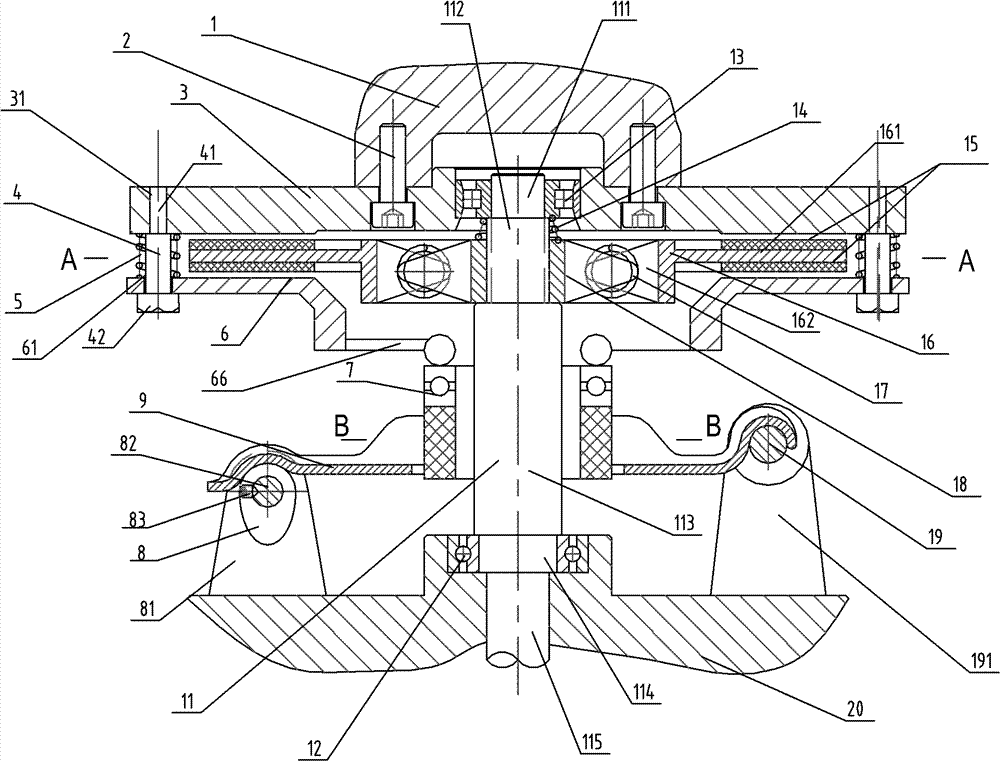
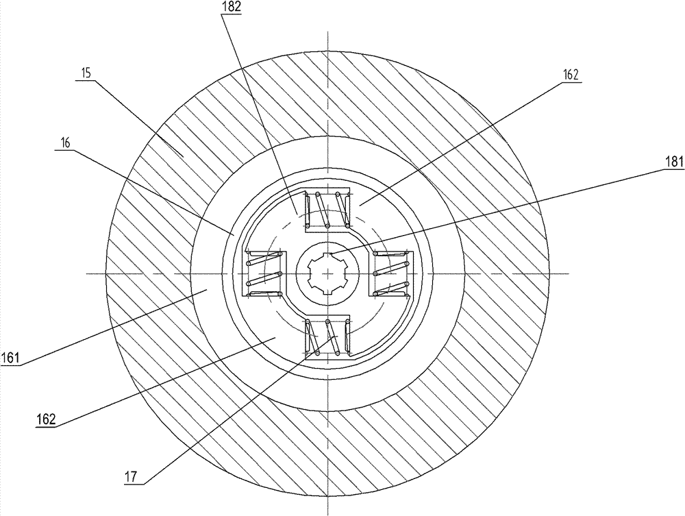
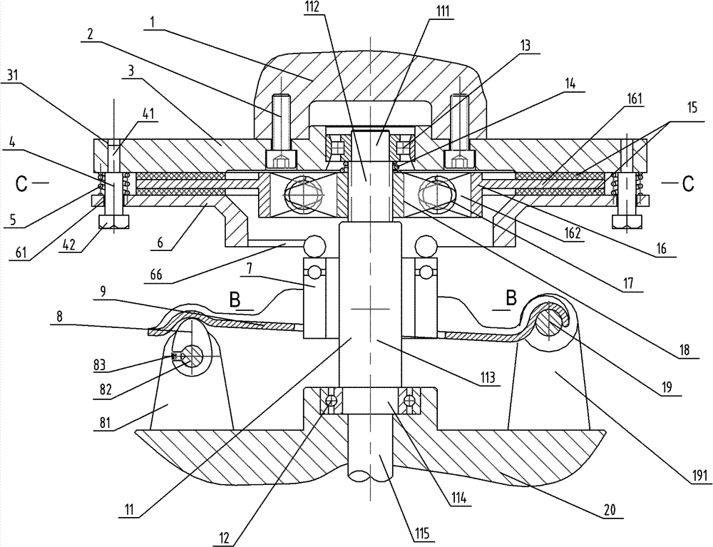
[0020] Figure 1~Figure 5 A composite clutch is given, which includes a main friction disc 3, a double-sided shaft friction disc 15, a secondary friction disc 6, a plane bearing fork body 7 and a base 20 arranged in sequence from top to bottom. The main friction disc 3 is fixedly connected with the bottom end of the high-speed moving part 1 through at least three countersunk screws 2 .

[0021] A guide rail 4 is set between the main friction disc 3 and the secondary friction disc 6, specifically as follows: three round holes 31 are provided near the outer circumference of the main friction disc 3, and three sets of guide rails 4 are installed correspondingly for fastening, The small head 41 of the guide plug 4 is used to be fastened and installed in the above-mentioned circular hole 31 (that is, the small head 41 of the guide plug 4 is fixedly connected with the main friction disc 3 ). The outer surface of the middle section of the guiding guide 4 is set with a return spring ...


PUM


Abstract

The invention discloses a composite clutch, comprising a main frictional disk (3) and the like. A guide column pin (4) is arranged between the main frictional disk (3) and an auxiliary frictional disk (6); a driven shaft (11) sequentially penetrates through a base (20), a plane bearing shifting fork body (7), the auxiliary frictional disk (6), a double-side shaft frictional disc (15) and the main frictional disk (3) from bottom to top, and the double-side shaft frictional disc (15) is in sliding connection with the driven shaft (11); the left side and the right side of the base (20) are respectively provided with a cam base (81) and a shifting fork fixing base (191), one end of a shifting fork (9) is rotationally connected with the shifting fork fixing base (191), and the other end of the shifting fork (9) is in contact with a cam (8) on the cam base (81); the shifting fork (9) is in sliding connection with the plane bearing shifting fork body (7); and an elastic contact block (66) abuts against the top surface of the plane bearing shifting fork body (7). The composite clutch can automatically align to be suitable for large-torque high-speed running.

Description

technical field [0001] The present invention relates to a kind of general mechanical product——clutch, particularly relates to a kind of compound clutch among them. Background technique [0002] In the known clutches, especially for high-torque chemical machinery and equipment operating at high speed, the two major problems of excessive transient impact force when the clutch contacts and the difficulty of achieving absolute coaxiality between the two parts of the relative clutch have not been effectively solved. . So far, there is no clutch that can do it at the same time: it has a buffer function and can be self-aligning to be suitable for high-torque chemical machinery and equipment running at high speed. Contents of the invention [0003] The technical problem to be solved by the present invention is to provide a composite clutch that has buffering capacity and can self-align to suit high-torque and high-speed operation. [0004] In order to solve the above-mentioned ...

Claims


Application Information

Patent Timeline
Patent Type & Authority Patents(China)
IPC IPC(8): F16D13/46F16D13/58F16D13/70
Inventor 焦磊张意立张鹏鹏王乐勤张志雄
Owner ZHEJIANG UNIV
Learn More