Two shot injection molded vehicle hitch step

a technology of injection molding and vehicle, which is applied in the direction of transportation and packaging, towing devices, and other domestic articles, can solve the problems of limited width of the hitch step, limited impact resistance of the rear of the vehicle, and prior hitch steps that add considerable weight to the vehicle, so as to increase the protection of the rear bumper and increase the friction surface

Active Publication Date: 2019-02-12
MACNEIL IP
View PDF31 Cites 6 Cited by
  • Summary
  • Abstract
  • Description
  • Claims
  • Application Information

AI Technical Summary

Benefits of technology

[0007]The present invention thus provides a polymer trailer hitch step that is wider in a transverse direction than prior polymer hitch steps, but which still is acceptably resistant to torsional force around the post axis and to downward deflection by a large load placed near an end of the step body. The second-shot compression zone of the disclosed hitch step provides a modicum of protection from rear impacts without irreversible damage to either the hitch step or to the vehicle to which it is mounted. The wider aspect of the disclosed hitch step affords increased protection of a rear vehicle bumper from rear impacts and expands the locations where a user can place his or her foot in gaining access to the upper reaches of the vehicle. The second shot top tread surface of a lower durometer material can also provide a higher friction surface under foot when standing on the step.

Problems solved by technology

However, the location of a rearward-facing hitch step means that it is often the point of first impact during a rear end collision.
Prior hitch steps therefore add considerable weight to the vehicle, and their ability to absorb, rather than transmit, impacts from the rear of the vehicle is limited.
While this trailer hitch step provides some protection against rear impacts and affords an area on which a user may step, the width of this hitch step is limited because of the torsional deformation and vertical deflection that would otherwise occur if a heavy load were placed on its transverse end.

Method used


Image

  • Two shot injection molded vehicle hitch step
  • Two shot injection molded vehicle hitch step
  • Two shot injection molded vehicle hitch step

Examples


Embodiment Construction

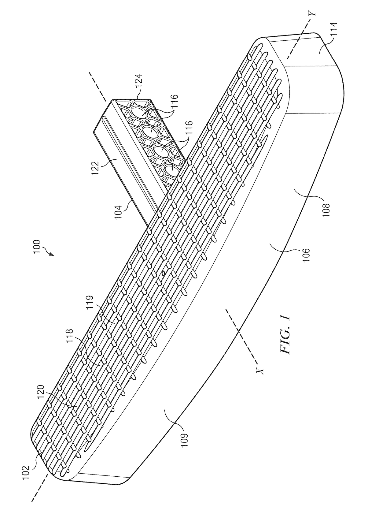
[0022]The present invention provides a hitch step for insertion into a hollow receiver type hitch on a vehicle. In the embodiment shown in FIG. 1, a hitch step, generally indicated at 100, includes a step body 102 and a post 104. Hitch step 100 is formed by injection molding in a two-shot process. The post 104 is formed from a first shot component molded from a polymer having a flexural modulus of at least 300,000 psi at 23° C. The polymeric compound generally has a high impact strength, ideally one that is rated as “No-Break” at 23° C. according to the Charpy Unnotched impact test criteria. All properties listed are for an ambient temperatures of 23° C. unless otherwise noted. The material can be a thermoplastic polyester blended with a thermoplastic polycarbonate. In one embodiment the first shot component is a polycarbonate (PC) / polybutylene terephthalate (PBT) polyester blend that has a flexural modulus of 305,000 psi at 23° C. and an impact strength of NB at 23° C. Key properti...


PUM

PropertyMeasurementUnit
flexural modulusaaaaaaaaaa
widthaaaaaaaaaa
weightaaaaaaaaaa

Abstract

A hitch step assembly comprises a first shot component injection molded from a first polymer compound with a high flexural modulus and a second shot component injection molded from a second polymer compound having a relatively low Shore D hardness but high elastic compression. A post and a step body core are molded from the first polymer compound. A shell of the step body is molded from the second polymer compound and is overmolded on the step body core. The shell forms a compression zone that provides some protection against rear impacts. The hitch step assembly exhibits satisfactory resistance to torsion around the hitch receiver axis and deflection, even when a width of the step body exceeds 10.7 inches and the weight of a large man is placed on the top surface of the hitch step near its end.

Description

BACKGROUND OF THE INVENTION[0001]Vehicles often have trailer hitch receivers mounted to the frame of the vehicle. These receivers are commonly rearward-facing and have an opening that accepts trailer hitch ball mounts, bike racks, cargo carriers and other hitch mounted accessories. One such accessory, a hitch step, provides a raised platform making the bed of a truck or the roof of a van or SUV more accessible. However, the location of a rearward-facing hitch step means that it is often the point of first impact during a rear end collision.[0002]Because many light trucks, vans and SUV's have wide bodies, it is useful for a hitch step to have a wider, stable platform upon which a user may step at a considerable distance from the hitch axis. A need also exists for a hitch step that absorbs force from the impact of a rear collision along a greater transverse range to better protect more of the vehicle rear bumper.[0003]Prior hitch steps are formed of metal, usually steel in order to wi...

Claims


Application Information

Patent Timeline
Patent Type & Authority Patents(United States)
IPC IPC(8): B60R3/00B29C45/14B60D1/58B29C45/16B29K21/00B29L9/00B29L31/30
CPCB60D1/58B29C45/14811B29C45/1671B60R3/007B29L2031/3005B29L2009/00B29C2045/1673B29K2021/003B29K2995/0046B29K2995/0082B29C45/1676
Inventor MACNEIL, DAVID F.MASANEK, JR., FREDERICK W.
Owner MACNEIL IP
Why Eureka
Try Eureka