
Long range bullet
- Summary
- Abstract
- Description
- Claims
- Application Information
AI Technical Summary
Benefits of technology
Problems solved by technology
Method used
Image

Examples
Embodiment Construction
[0019]The invention also has reference to flat base bullets. The trajectory of flat based bullets can also be similarly improved by employing the “narrow” or the “recess” for such a bullet.
[0020]The invention is now described by way of example with reference to the further accompanying drawings.
[0021]In the drawings:
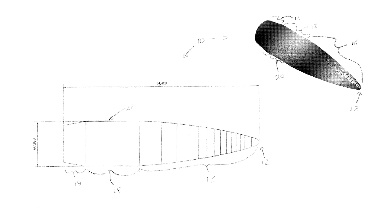
[0022]FIG. 1 shows a profile and perspective view of one embodiment of a long range bullet, in accordance with the invention;
[0023]FIG. 2 shows dimensions of the bullet shown in FIG. 1;
[0024]FIG. 3 shows a profile and perspective view of another embodiment of a long range bullet, in accordance with the invention;
[0025]FIG. 4 shows dimensions of the bullet shown in FIG. 3;
[0026]FIG. 5 shows a profile and perspective view of another embodiment of a long range bullet, in accordance with the invention;
[0027]FIG. 6 shows dimensions of the bullet shown in FIG. 5;
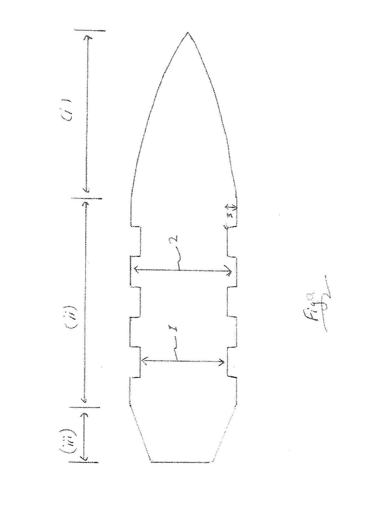
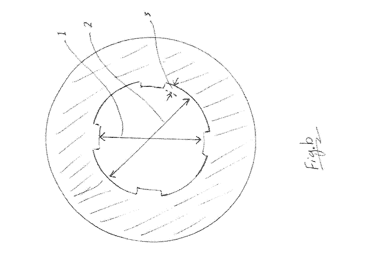
[0028]FIG. 7 shows a bullet having multiple narrows, each having a depth of 0.02 mm below the groove diameter.
[0029]...
PUM
 Abstract
Description
Claims
Application Information