Magnetic resonance imaging apparatus

A technology of magnetic resonance imaging and imaging unit, applied in magnetic resonance measurement, measurement using nuclear magnetic resonance image system, measurement device, etc., can solve problems such as the state where the magnetization has not been fully restored

Inactive Publication Date: 2011-08-03
TOSHIBA MEDICAL SYST CORP
View PDF7 Cites 13 Cited by
  • Summary
  • Abstract
  • Description
  • Claims
  • Application Information

AI Technical Summary

Problems solved by technology

When this non-contrast MRA is performed using biological information (such as respiratory cycle), there is a problem that, for example, when the patient's respiratory cycle becomes extremely short, imaging is performed without sufficient magnetization recovery.

Method used


Image

  • Magnetic resonance imaging apparatus
  • Magnetic resonance imaging apparatus
  • Magnetic resonance imaging apparatus

Examples


no. 2 Embodiment approach

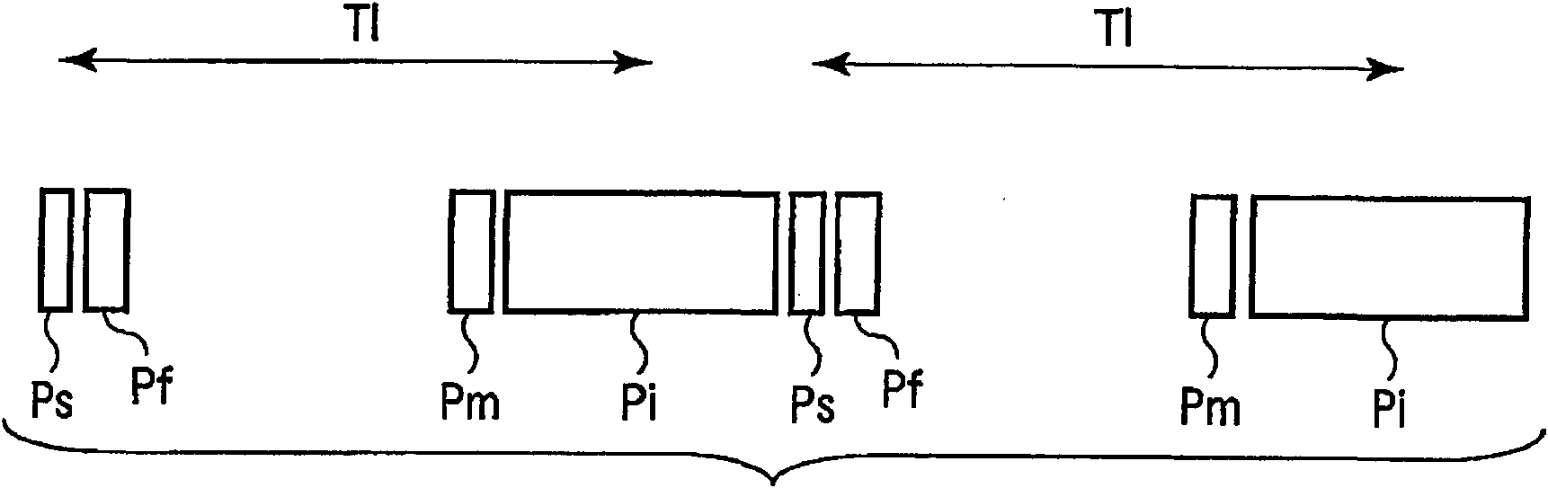
[0086] Next, the magnetic resonance imaging apparatus according to the second embodiment of the present invention will be described. The magnetic resonance imaging apparatus according to this embodiment is an apparatus that applies temporal adjustment processing to non-contrast MRA imaging. That is, in the magnetic resonance imaging apparatus according to the present embodiment, at least one of TI, the flip angle of the IR pulse, and the flip angle of the RF pulse for imaging is adjusted in accordance with changes in biological signals such as the respiratory cycle to obtain Non-contrast MRA that has less influence due to physical activity. The above-mentioned TI is the period from the time the inversion recovery pulse (IR pulse) for tag addition is applied to the time the first RF pulse for imaging is applied . Such a non-contrast MRA imaging method is considered from the perspective of marking a certain area of ​​the subject in time and space by applying IR pulses, and is so...

Deformed example 1

[0109] In the second embodiment, a sequence for performing imaging using the three-dimensional SSFP (Steady-State Free Precession: Steady-State Free Precession) method (refer to Picture 11 , Picture 12 ). However, the present invention is not limited to this example, for example, three-dimensional FSE (Fast Spin-Echo: Fast Spin-Echo) method, three-dimensional FASE (Fast Advanced Spin-Echo: Advanced Fast Spin-Echo) method, etc. can also be used. Scan sequence for imaging. Moreover, the image collection method can be any one of a single shot or multiple shots. If for example figure 2 The example of is in accordance with the sequence of the single-shot 3D SSFP method, the first slice encoding is executed in imaging I, and then the second slice encoding is executed in imaging II. On the other hand, if for example Picture 11 , Picture 12 The example is in accordance with the sequence of the three-dimensional SSFP method of multiple imaging (2 imaging), the first imaging of the...

Deformed example 2

[0111] In the second embodiment, the case where the biological signal is the respiratory cycle is exemplified. However, without restricting to this example, the technical idea of ​​the present invention is also applicable to non-contrast MRA imaging using ECG waveforms or pulsation waveforms as biological signals, for example.

[0112] According to the above-mentioned configuration, when performing non-contrast MRA imaging, the variation of the respiratory cycle is measured, and the waiting time from the tag-added pulse to the imaging pulse and the flip angle of the tag-added pulse are performed in accordance with the variation. The suppression and the control of the flip angle of the imaging pulse make the time phase of dynamic imaging correspond to the cardiac time relatively, and the imaging conditions can be scheduled according to the pattern of respiratory cycle changes. Therefore, it is possible to correct the positional deviation in the dynamic phase direction in non-contr...


PUM


Abstract

Before myocardium perfusion imaging, the variation of position in the dynamic time-phase direction due to a respiratory body motion of the subject is detected, and the slice excitation position and the data collection position are made to follow up the body motion according to the variation. For the follow-up, a saturation pulse of space nonselection and a local selection pulse for flip back of the flip angle attributed to the saturation pulse of space nonselection are applied to the region to which a probe pulse for detecting the body motion of the subject before the heart is imaged is applied before the probe pulse is applied, thereby measuring the body motion.

Description

Technical field [0001] The invention relates to a magnetic resonance imaging device that can perform high-precision myocardial perfusion imaging, non-contrast MRA (magnetic resonance angiography), and can improve the diagnostic performance of the heart. Background technique [0002] A magnetic resonance imaging device is a device that uses the phenomenon of resonantly absorbing the energy of a high-frequency magnetic field rotating at a specific frequency when the core group with an inherent magnetic moment is placed in a uniform static magnetic field, and the chemical and Physical microscopic information imaging, or observation of chemical shift spectrum. Such a magnetic resonance imaging device is extremely effective as a method for obtaining an anatomical cross-sectional view of the human body in a non-invasive manner. In particular, it is widely used effectively as a diagnostic device for the central nervous system such as the brain covering the bone. On the other hand, due...

Claims


Application Information

Patent Timeline
Patent Type & Authority Applications(China)
IPC IPC(8): A61B5/055G01R33/48
CPCA61B5/7285A61B5/7207G01R33/56366G01R33/5613G01R33/56509G01R33/4828G01R33/5676A61B5/055G01R33/56333G01R33/4838G01R33/5607G01R33/5673
Inventor 葛西由守
Owner TOSHIBA MEDICAL SYST CORP
Why Eureka
Try Eureka