Eureka AIR delivers breakthrough ideas for toughest innovation challenges, trusted by R&D personnel around the world.

Umbrella dewatering machine and water throwing balance mechanism thereof

A technology of balance mechanism and dehydrator, which is applied in the direction of dryers, types of dried products, and dried solid materials, etc. It can solve problems such as unstable rotation of the water rejection device and unstable use of the umbrella dehydrator of the water rejection device, so as to avoid Strong vibration, the effect of improving stability

Inactive Publication Date: 2011-08-10
廖智丰
View PDF3 Cites 8 Cited by
  • Summary
  • Abstract
  • Description
  • Claims
  • Application Information

AI Technical Summary

Problems solved by technology

The water throwing device of a general umbrella dehydrator is directly fixedly connected to the frame. However, during high-speed rotation, the entire water throwing device including the motor will vibrate violently, mainly due to the vibration generated by the eccentricity of the umbrella in the water throwing box, and the vibration is directly transmitted to Frame, the frame interacts with the ground and then reacts on the water throwing device, resulting in unstable rotation of the water throwing device, resulting in unstable use of the water throwing device and the entire umbrella dehydrator

Method used


Image

  • Umbrella dewatering machine and water throwing balance mechanism thereof
  • Umbrella dewatering machine and water throwing balance mechanism thereof
  • Umbrella dewatering machine and water throwing balance mechanism thereof

Examples


Embodiment Construction

[0024] The specific implementation manner of the present invention will be further described below in conjunction with the accompanying drawings.

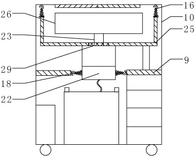
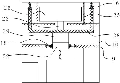
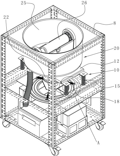
[0025] Such as figure 1 As shown, a water rejection balance mechanism 10 is used to connect the frame 8 and the water rejection device 10 in an umbrella dehydrator, and the water rejection balance mechanism 10 includes a base 12 fixedly connected to the middle part of the water rejection device 20, The elastic component group connecting the base 12 and the frame 8 to make the water throwing device 20 supported on the frame 8 . The water throwing device 20 can be balancedly supported on the frame 8 through the elastic component group, so as to ensure the stable operation of the water throwing device 20 and prevent the vibration generated by the water throwing device 20 from being directly transmitted to the frame 8, so as to achieve the effect of shock absorption.

[0026] In the umbrella dewatering machine, a set of elastic parts ...


PUM


Abstract

The invention discloses a water throwing balance mechanism for connecting a frame with a water throwing device in an umbrella dewatering machine. The water throwing balance mechanism comprises a base and an elastic component group, wherein the base is fixedly connected with the middle part of the water throwing device, and the elastic component group is connected with the base and the frame and ensures that the water throwing device is supported on the frame. The elastic component group and the base which are connected with each other are arranged to form the water throwing balance mechanism,the base is fixedly connected with the middle part of the water throwing device, the base is connected with the elastic component group and the elastic component group is also connected with the frame so that the water throwing balance mechanism and the water throwing device constitute a suspending connection structure, the suspending connection structure is then connected with the frame to form a suspension-type installation structure, vibration generated by the water throwing device is absorbed by the elastic component group to prevent the vibration from being directly transferred to the frame, and thus the stability of the umbrella dewatering machine is greatly improved and violent vibration is avoided. The invention further discloses an umbrella dewatering machine having the water throwing balance mechanism, and the water throwing balance mechanism plays a vibration-preventing role of preventing the vibration of the water throwing device from being transferred to the frame.

Description

technical field [0001] The invention relates to an umbrella dehydrator. The invention also relates to a water-spinning balance mechanism for an umbrella dewatering machine. Background technique [0002] On rainy days, in office buildings, shopping malls and other places with a large flow of people, rainwater from umbrellas dripping onto the ground will make the ground slippery, prone to accidents such as falls, and at the same time have an impact on the environment of buildings, shopping malls, etc. In addition, it is very inconvenient for people to go shopping with wet umbrellas. In order to solve the above problems, the common solution is to use plastic bags to hold wet umbrellas, but the plastic bags have a great impact on the environment, and when the quality of the plastic bags is not good or damaged, the rain will also cause the ground to be slippery . Based on this, the umbrella dehydrator came into being. [0003] In the umbrella dehydrator, the umbrella is clamp...

Claims


Application Information

Patent Timeline
IPC IPC(8): F26B5/08A45B25/28
CPCA45B25/28F26B25/08F26B5/08F26B2210/10
Inventor 廖显钊廖智丰陈灼森
Owner 廖智丰
Why Eureka
Eureka Blog
Learn More