Rigid sectional mold damp continuous regulating device for wind-tunnel test

A technology for regulating devices and wind tunnel tests, which is applied in measuring devices, aerodynamic tests, and testing of machine/structural components, etc. It can solve problems such as increasing the damping of segmental model systems, large lower limit values ​​of damping, and long adjustment times , to achieve the effects of saving test time, stable damping ratio and high adjustment efficiency

Active Publication Date: 2011-08-10
HUNAN UNIV +1
View PDF3 Cites 24 Cited by
  • Summary
  • Abstract
  • Description
  • Claims
  • Application Information

AI Technical Summary

Problems solved by technology

[0004] At present, there is no uniform way to adjust the damping ratio of the segmental model system. Generally, mechanical friction, rubber strips, etc. are used. However, there is no quantitative or even qualitative adjustment criterion for adjusting the damping method similar to the above. The ratio is more accurate and consistent, only the method of multiple attempts can be adopted, and there is a problem that the adjustment time is too long, which increases the cost of the test
In addition, in the tests requiring low damping, the above-mentioned mechanical friction and rubber strips are often used as additional contact facilities, which increase the damping of the segmental model system, making the lower limit of the damping of the system itself too large to be possible. Achieving a lower target damping value; in the test of damping ratio versus structural vibration, since the damping ratio of the segmental model system is closely related to the amplitude, it is difficult to keep the mechanical damping of the system constant during the model vibration process, so that the test results can be The reliability is reduced; especially when the damping ratio needs to be adjusted continuously in a large range, the above damping adjustment method is basically not feasible

Method used


Image

  • Rigid sectional mold damp continuous regulating device for wind-tunnel test
  • Rigid sectional mold damp continuous regulating device for wind-tunnel test
  • Rigid sectional mold damp continuous regulating device for wind-tunnel test

Examples


Embodiment Construction

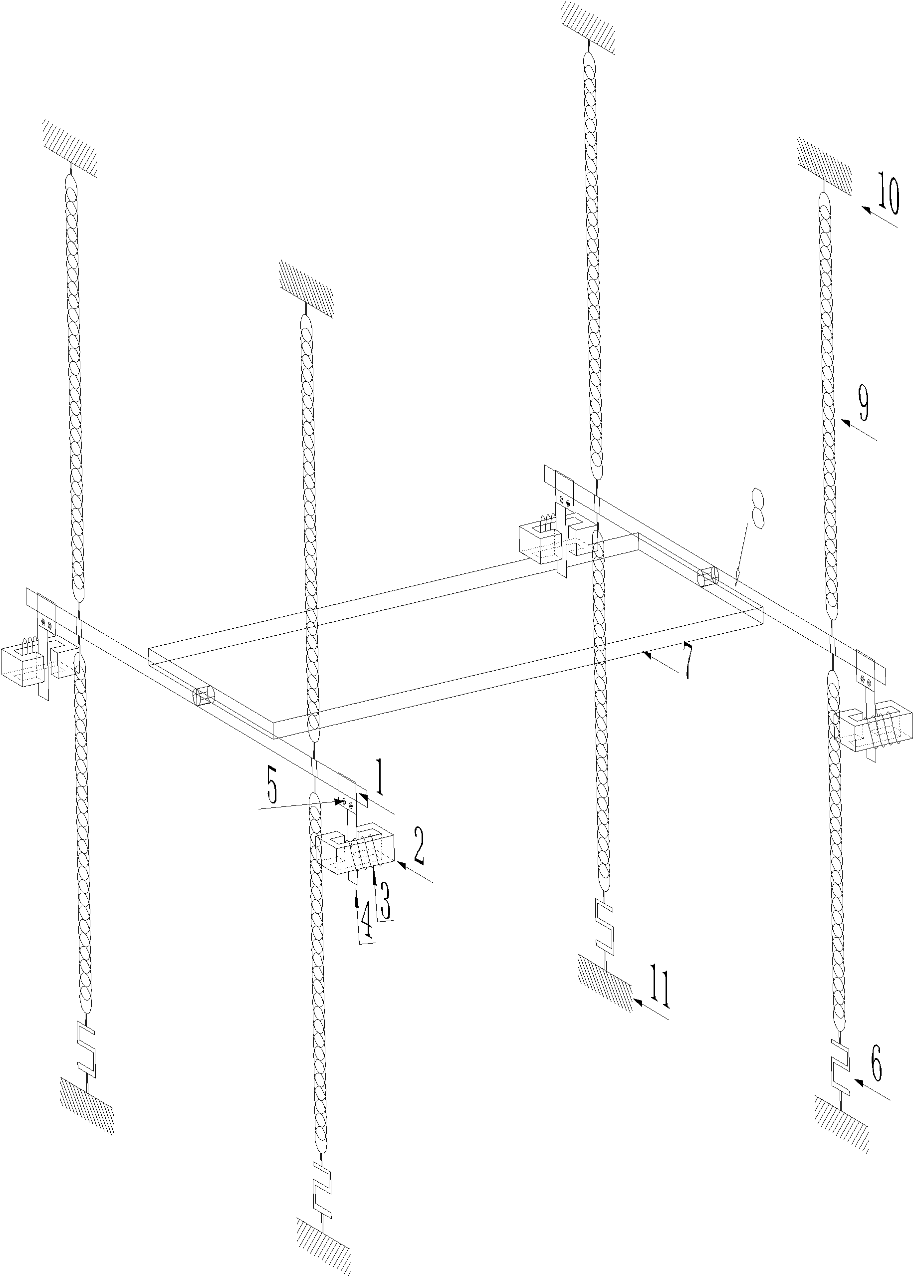
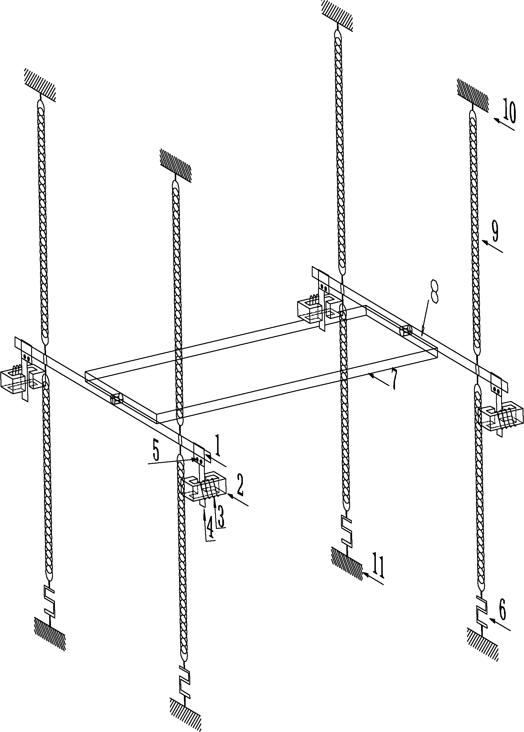
[0024] Such as figure 1 , figure 2 As shown, the two ends of the segment model 7 are respectively fixedly connected with two rigid links 8, and the two ends of each rigid link 8 are respectively connected with the corresponding springs 9; the upper ends of each spring 9 are fixedly connected with the inherent boundary 10, and each spring The lower end of 9 is connected to the base 11 through the force sensor 6, and an electromagnetic damping adjuster comprising a copper sheet 4 and a rectangular ring silicon steel magnetic core 2 with an opening is respectively installed at both ends of each rigid connecting rod 8.

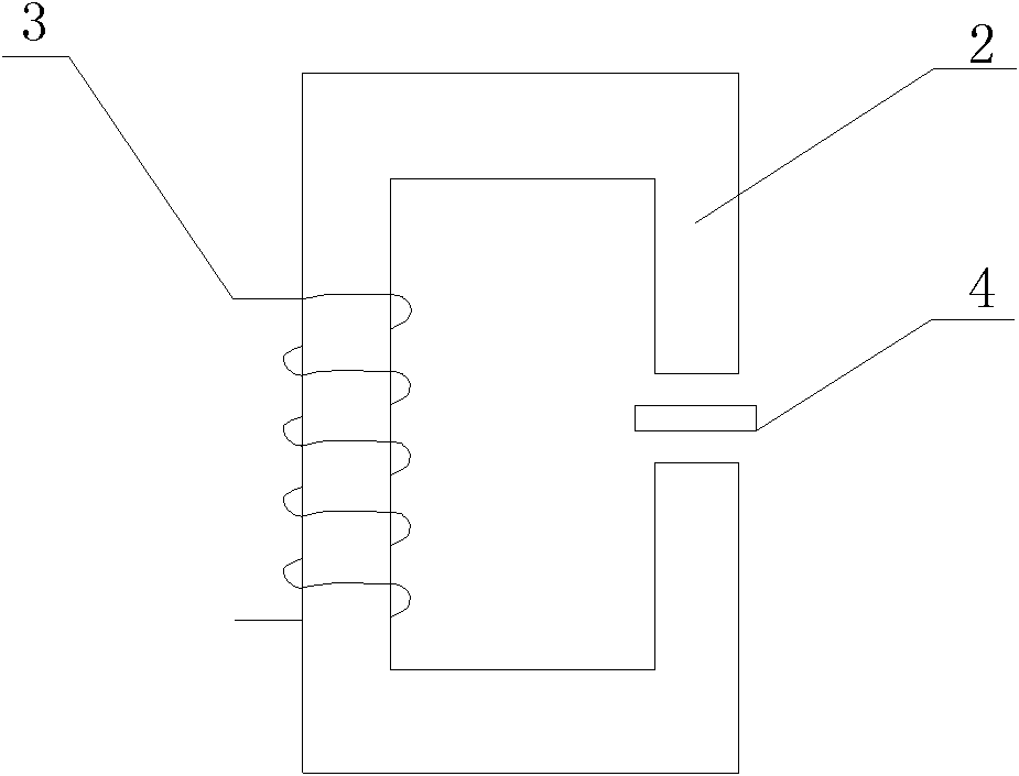
[0025] A coil 3 is wound on the silicon steel magnetic core 2, and the coil 3 is connected to a power supply with adjustable current through a wire. The silicon steel magnetic core 2 is fixed relative to the base 11; the copper sheet 4 connected to the end of the rigid connecting rod 8 is placed The opening of the silicon steel magnetic core 2 can move up and do...


PUM


Abstract

The invention relates to a rigid sectional mold damp continuous regulating device for a wind-tunnel test. The device comprises a sectional mold, wherein two ends of the sectional mold are respectively and fixedly connected with two rigid connecting rods correspondingly; two ends of each rigid connecting rod are respectively connected with corresponding springs; the upper end of each spring is fixedly connected with an intrinsic boundary, and the lower end of each spring is connected with a base. The device is characterized in that the end part of the rigid connecting rod is provided with an electric magnetic damper regulator. According to the invention, through continuously regulating the input current, the continuous regulating of the ratio of the vertical damping to the torsion damping of the sectional mold system is realized, so that the debugging process of the damping ratio is simplified, and the problem of unstable damping ratio in the test process is avoided.

Description

technical field [0001] The invention relates to a wind tunnel test device, in particular to a wind tunnel test rigid section model damping continuous adjustment device. Background technique [0002] Bridges in the world are developing in the direction of long-span and softness, and wind load has become a key factor to ensure the safety design of bridge structures. For example, as early as 1940, the wind-induced flutter of the old Tacoma Channel suspension bridge in the United States shocked the bridge industry. collapse event, and its main girder had already experienced serious vertical vortex induced resonance phenomenon at very low wind speed before the flutter damage occurred. Severe vertical vortex-induced vibration occurred at a wind speed of s, with a maximum bilateral amplitude of 76cm, and the wind speed range of vortex vibration continued to 15.6m / s. At present, the research on the wind-induced performance of bridges to be built or completed includes four methods: ...

Claims


Application Information

Patent Timeline
Patent Type & Authority Applications(China)
IPC IPC(8): F16F15/03F16F15/18G01M9/02
Inventor 陈政清周帅牛华伟汪志昊
Owner HUNAN UNIV
Why Eureka
Try Eureka