Sealing chain

A technology for sealing parts and outer chain links, applied in the field of sealing chains, can solve the problem of difficulty in increasing the spherical shape r, etc., and achieve the effects of suppressing uneven contact pressure, improving tensile strength, and alleviating stress concentration

Active Publication Date: 2011-08-10
DAIDO KOGYO CO LTD
View PDF4 Cites 3 Cited by
  • Summary
  • Abstract
  • Description
  • Claims
  • Application Information

AI Technical Summary

Problems solved by technology

On the other hand, if the length of the radial direction of the first lip portion 32a becomes longer, the spherical shape r' becomes larger, and the width difference between the above-mentioned radial base end portion and the middle portion can be increased, but the length dimension is due to the assembled There are restrictions on the relationship between the plates 6 and 8 with narrow width. Figure 10 In the case of the shape of (b), it is difficult to enlarge the spherical shape r'

Method used


Image

  • Sealing chain
  • Sealing chain
  • Sealing chain

Examples


Embodiment Construction

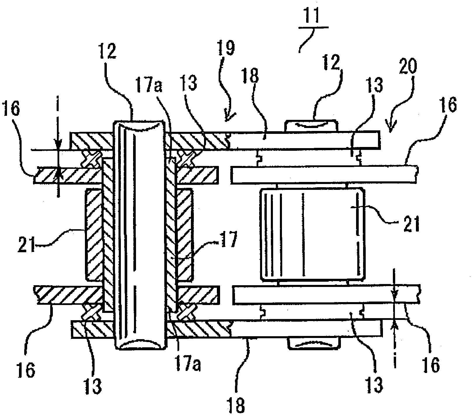
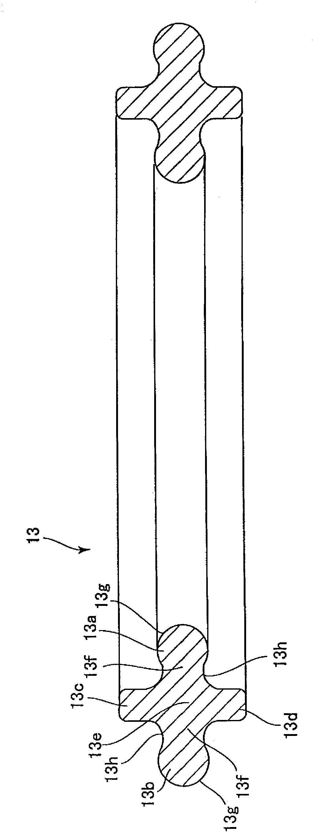
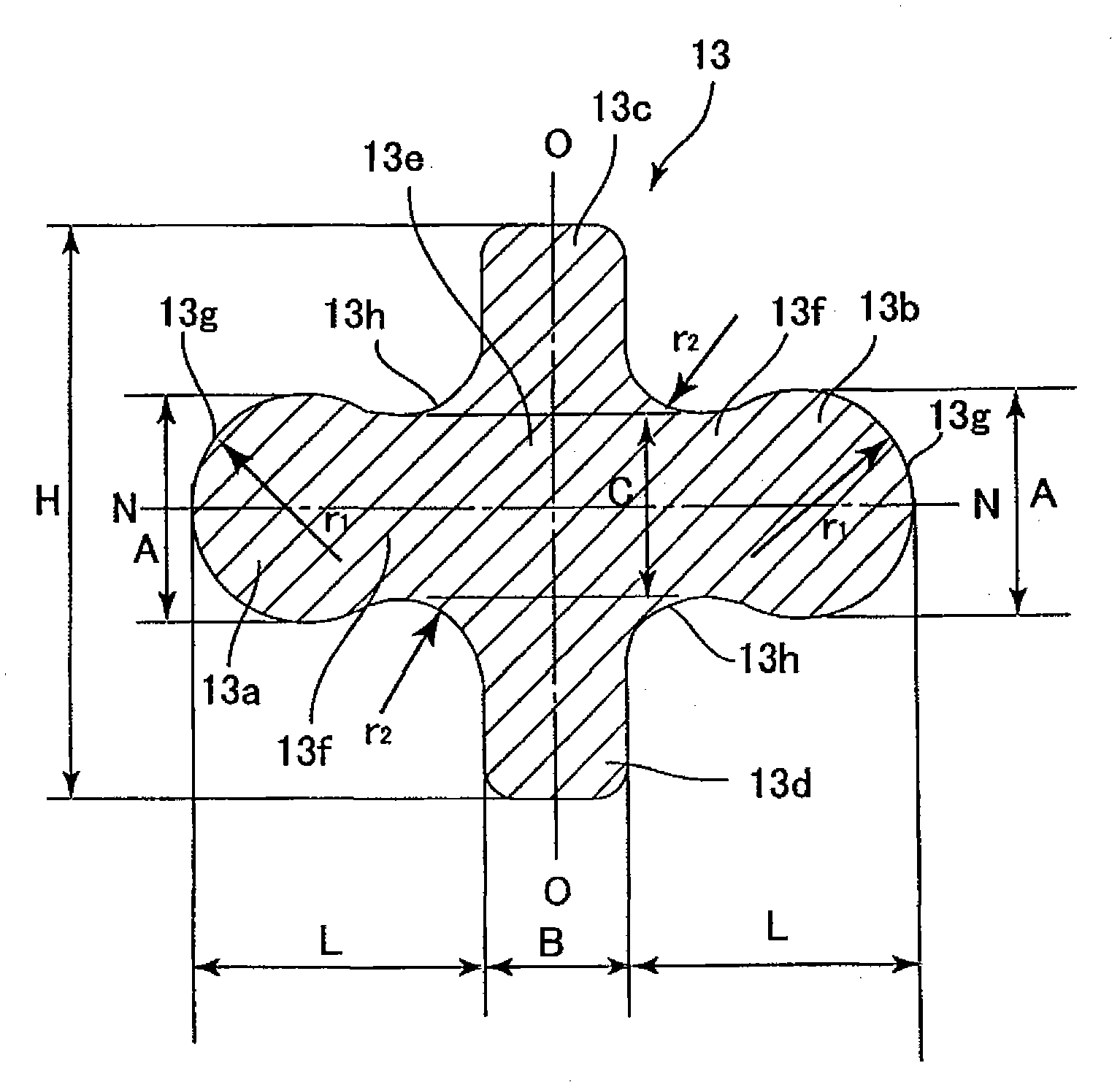
[0046] Below, use Figure 1 to Figure 8 , to describe the embodiment of the present invention. Such as figure 1 Shown, this sealing chain 11 is, for the outer (pin) chain link 19 that forms by the pin 12 connecting the two ends of two oval outer (pin) link plates 18 made of steel, and the outer (pin) link 19 formed by the bushing 17 The inner (roller) link 20 formed by connecting the two ends of the inner (roller) link plates 16 having the same shape is connected in a ring shape by inserting the pin 12 into the bush 17 . In addition, the roller 21 is rotatably fitted to the bush 17 , and the bush 17 is fixed so as to protrude by a predetermined amount from the outer surface of the inner link plate 16 . Furthermore, a seal member (seal ring) 13 according to the present embodiment is interposed between the inner link plate 16 and the outer link plate 18 so as to surround the protruding portion 17 a of the bush 17 . The clearance i{between the outer link plate 18 and the inne...


PUM


Abstract

The invention discloses a sealing chain, which can appropriately ensure the contacting pressure between a first lip part (13a) of a sealing component (13) and a plate, inhibits the unevenness of the contacting pressure even when the sealing chain is obliquely erected and the sealing compression amount becomes uneven, and eases the stress concentration of each lip part (13a, 13b, 13c, 13d) under the state that the sealing component (13) is compressed. The first and second lip parts (13a, 13b) extending along a radial direction from a central base (13e) are characterized in that the widths (C, A) of the radial middle parts are larger than the width (B) of the third and the fourth lip parts (13c, 13d); a necking part (13f) having a width being smaller than the radial middle part is disposed at the radial base end; the necking part (13f) is provided with a bending recessed surface (13h).

Description

technical field [0001] The present invention relates to a seal chain used as a transmission chain of transportation machinery such as motorcycles and general industrial machinery, and also as a conveying chain such as a conveyor belt, especially a seal chain using a cross-section roughly in the shape of a plus sign (ten) in a natural state. Sealed chain of components. Background technique [0002] The present applicant proposes a method of manufacturing a sealed chain using an annular sealing member having a lip that hangs down in the radially inner direction in a natural state, and the sealing member is twistedly attached to the inner link plate and the inner link plate with the lip as a fulcrum. Between the outer link plates (refer to Patent Document 1). The manufacturing method is as Figure 9 As shown, first, as Figure 9 As shown in (a), the first lip portion 3a of the sealing member 3 is positioned between the front end of the bushing protrusion 7a and the outer link ...

Claims


Application Information

Patent Timeline
Patent Type & Authority Applications(China)
IPC IPC(8): F16G13/06
Inventor 酒井健成
Owner DAIDO KOGYO CO LTD
Why Eureka
Try Eureka