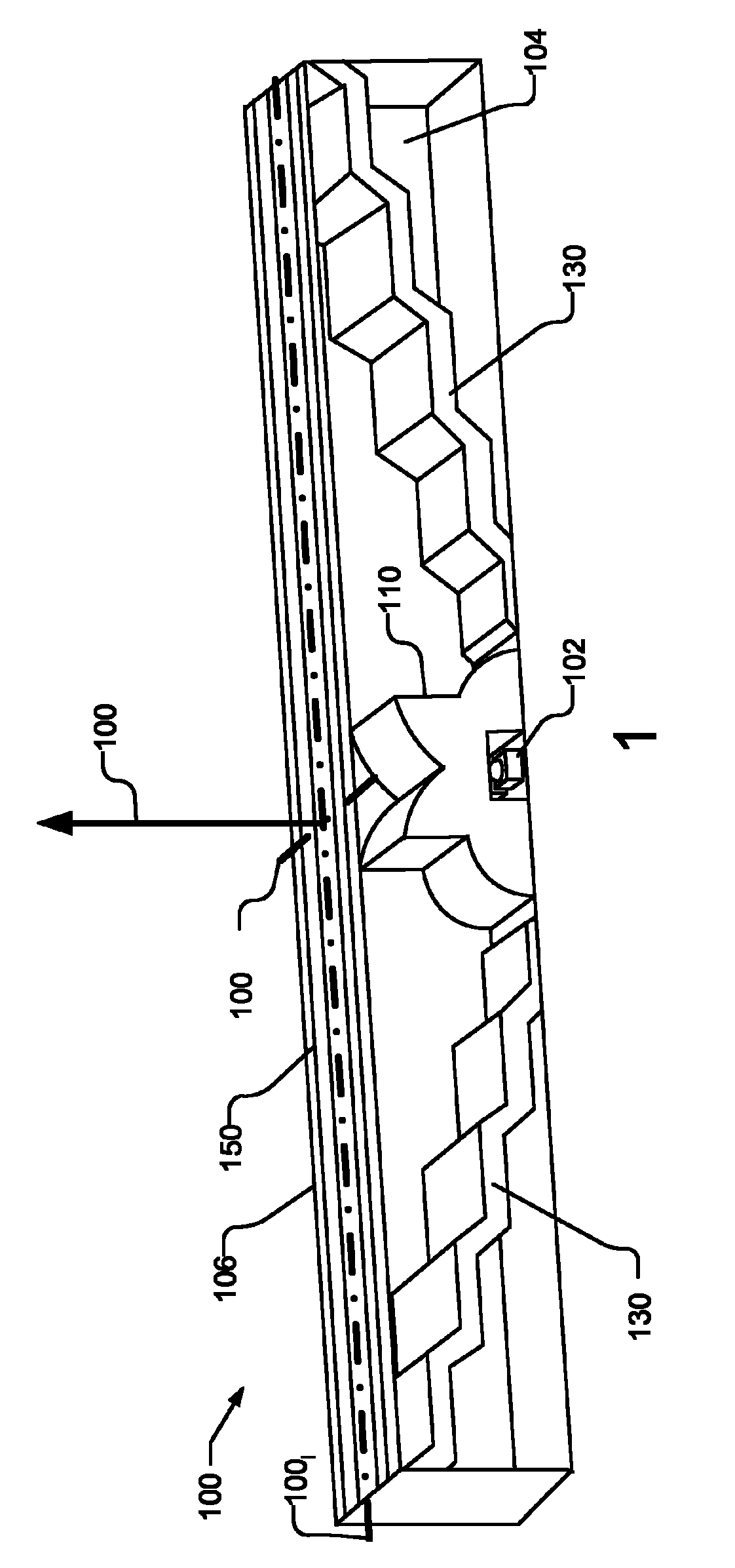
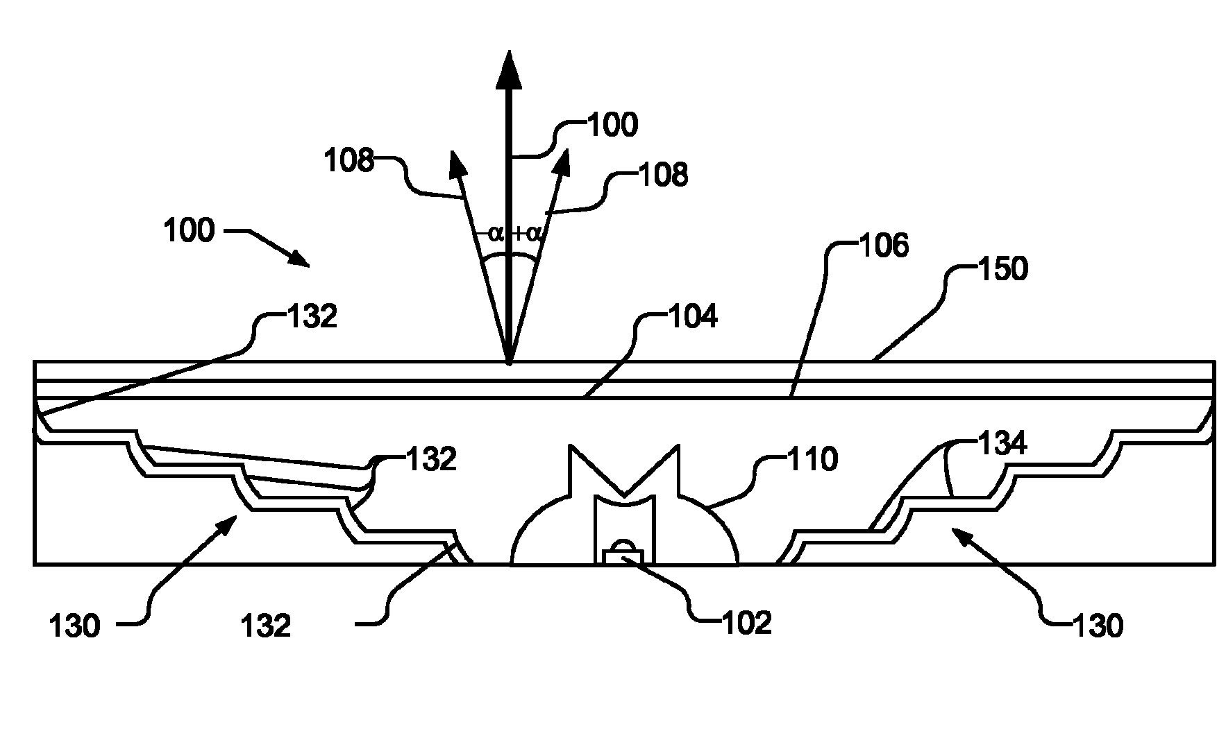
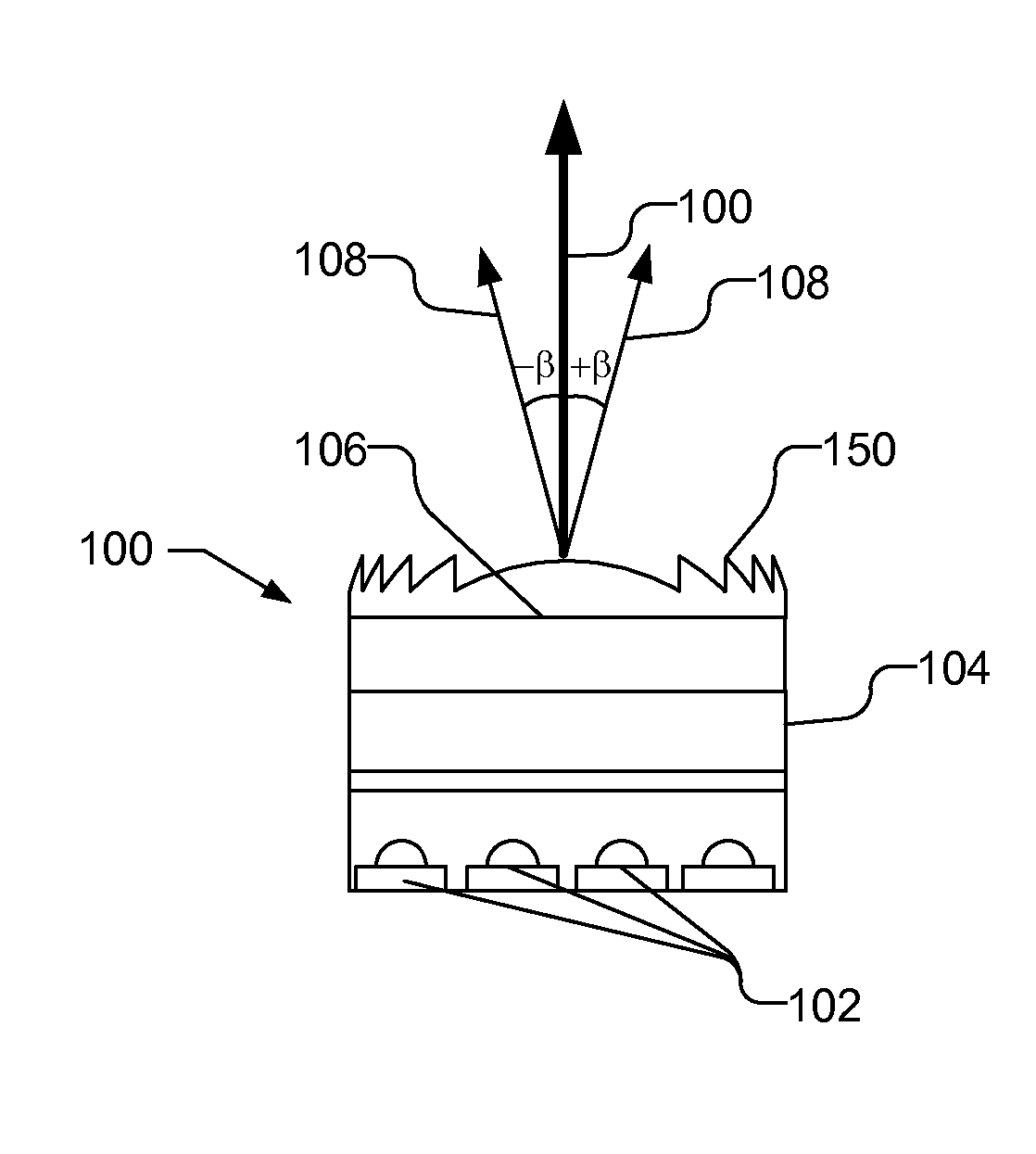
[0010] figure 1 A perspective view illustrating an optical system 100 that may be used with a compact light source, such as a light emitting diode (LED) 102 , in accordance with one embodiment of the present invention. It can be seen that the optical system 100 has a narrow aspect ratio, for example 3:1, but this can be changed as desired. figure 2 and 3 are respectively along the major axis 101 of the optical system 100 long and minor axis 101 short side view. Long axis 101 long and minor axis 101 short orthogonal to each other. The optical system 100 causes the light emitted from the light source to be distributed substantially uniformly throughout the exit window 106 of the optical system 100 and to be strictly collimated, ie directed in a direction substantially perpendicular to the plane of the exit window 106 . It is widely understood in the art that collimated light is not perfectly collimated, but may have some degree of angular spread.
[0011] like image 3 As illustrated, the optical system 100 can be used with multiple light sources, for example, disposed in the same plane and at a distance from the minor axis 101 of the optical system 100 short Four LEDs 102 in parallel lines. Any conventional LED 102 or other light source may be used with the present invention. In one embodiment, LED 102 produces a substantially Lambertian radiation pattern and may be a phosphor-converted blue LED that produces white light or light of any color. Preferably, the light source used with optical system 100 produces short substantially uniform radiation. A substantially homogeneous illumination may, for example, be uniform enough that interfering strong light changes cannot be observed with the naked eye. It should be understood that while there may be some variation in illumination, this variation is either imperceptible to the naked eye or not intrusive.
[0012] Optical system 100 includes a cylindrical side-emitting lens 110 which, in accordance with one aspect of the invention, redirects light from LED 102 to a direction aligned with major axis 101. long A direction parallel to the exit surface 106. Figure 4 A perspective view of one embodiment of a cylindrical side-emitting lens 110 is illustrated. The cylindrical side-emitting lens 110 has a section along a plane defined by the central axis 113 and the optical axis 112 of the lens 110, which section may be similar in shape to a rotationally symmetric one such as that described in US6679621, incorporated herein by reference. Traditional side-firing lenses. Along this section, the cylindrical side-emitting lens 110 includes a V-shaped top 110 top , the V-shaped top has a reflective (eg, total internal reflection) surface I and a refractive surface H. The reflective surface I and several refractive surfaces form several planes, and the refractive surfaces are inclined at an angle with respect to the central axis 113 . lower part 110 lower There is a refractive surface 116 extending as a smooth curve from the refractive surface H to the bottom surface 118 of the lens 110 .
[0013] LED 102 is positioned inside cavity 120 in lens 110 . The inner surface of the cavity 120 is composed of two planar surfaces 121 and one substantially spherical surface 122 . Cavity 120 may contain a gas, may be a vacuum, or may contain a non-gaseous material, such as a solid, liquid, or gel, that may assist in light extraction. The outer sides of cavity 120 (ie, sides orthogonal to reflective and refractive surfaces I, H, and 116 ) may be covered with a reflective film, either on lens 110 or on the sides of optical system 100 . A fraction of the light incident on the reflective surface I may be transmitted and used to illuminate the exit face 106 . Light entering lens 110 from cavity 120 and directly incident on reflective surface I is reflected to first refractive surface H and refracted to exit lens 110 in a direction substantially parallel to optical axis 112 . Light entering the lens 110 from the cavity 120 that is directly incident on the second refractive surface 116 is also refracted so as to exit the lens 110 in a direction substantially parallel to the optical axis 112 .
[0014] exist Figure 4 As can be seen in , the cross-sectional shape of the cylindrical side-emitting lens 110 along the plane defined by the optical axis 112 and the central axis 113 is the same cross-sectional shape at every point along the horizontal axis 114 orthogonal to the optical axis 112 . Thus, unlike conventional side-emitting lenses, the cylindrical side-emitting lens 110 is not rotationally symmetric. It should be understood that the cross-sectional shape of the side-emitting lens 110 is exemplary and other cross-sectional shapes of the side-emitting lens may be used as desired. The lens 110 may be produced using, for example, vacuum casting or injection molding, using materials such as polycarbonate, PMMA or other suitable materials.
[0015] like figure 1 As shown, a reflector 130 is present in the optical system 100 to redirect the side-emitting light from the cylindrical side-emitting lens 110 to the front direction 100 forward , which is perpendicular to the major axis 100 long and minor axis 100 short. Optical system 100 includes two stepped multifocal line reflectors 130 a and 130 b , collectively referred to as reflectors 130 , positioned on opposite sides of cylindrical side-emitting lens 110 . If desired, only one reflector 130 may be used, with the cylindrical side-emitting lens 110 positioned at one end of the optical system 100 . Cylindrical side emitting lens 110 will not need to be symmetrical across the minor axis. In another embodiment, the reflector 130 may be a continuous reflector with an appropriate shape (eg, a spline) over its entire length to redirect side emitted light to forward light.
[0016] Reflector 130 includes a plurality of reflector surfaces 132 positioned at different distances from cylindrical side-emitting lens 110 . Additionally, the reflector surface 132 is positioned relative to the forward direction 100 forward Measured at different heights. It can be seen that the highest reflector surface 132 top is also farthest from the cylindrical side-emitting lens 110, and the lowest reflector surface 132 bottom closest to the side emitting lens 110 . The reflector surfaces 132 may be interconnected, for example via steps 134 as illustrated, or alternatively may be separate and supported by the sidewall 104 of the optical system 100 . Also, it can be found in figure 2 As seen more clearly in the side view shown, the reflector surface 132 is parabolic in shape. The focal length of each parabolic reflector surface 132 is chosen to correspond to the distance between the reflector surface 132 and the cylindrical side-emitting lens 110 . The configuration of the reflector surfaces 132 (i.e., their parabolic shape and their position, including height and distance from the cylindrical side-emitting lens 110) redirects the side-emitting light into forward light, which is identical to that produced by the cylindrical side-emitting lens 110. The part of the light emitted by the side-emitting lens 110 along the forward direction is combined to form a long ) substantially uniform irradiation. Substantially uniform illumination may be, for example, sufficiently uniform that disturbing strong light changes cannot be observed by the naked eye. It should be understood that while there may be some variation in illumination, this variation is either imperceptible to the naked eye or not intrusive.
[0017] Similar to the cylindrical side-emitting lens 110, the reflector 130 may be produced using, for example, vacuum casting or injection molding, using materials such as polycarbonate, PMMA or other suitable materials.
[0018] With the combined cylindrical side-emitting lens 110 and stepped multifocal line reflectors 130a and 130b, the light is substantially uniform along the length of the optical system and strictly collimated to the forward direction 100 forward. like figure 2 stated, relative to the major axis and positive 100 forward , the light is substantially collimated, i.e., the light is in the forward direction by 100 forward and major axis 100 longThe defined plane has an angular spread α of ±15 degrees around the positive direction.
[0019] The optical system 100 also includes a cylindrical Fresnel lens 150 at the exit surface 106, so that in the forward direction 100 forward and minor axis 100 short Defined plane collimation in the positive direction of 100 forward ambient light such as image 3 explained. It should be understood that image 3 Optical system 100 is illustrated along the minor axis, but reflector 130 is not shown for simplicity. exist image 3 Cylindrical Fresnel lens 150 has a conventional Fresnel configuration when viewed in section along the minor axis as illustrated in . Cylindrical Fresnel lens 150 has the same cross-section at every point along the major axis. Cylindrical Fresnel lens 150 collimates the light substantially to the forward direction l00 with respect to the minor axis forward , that is, the light has an angular spread β of ±15 degrees around the positive direction.
[0020] Similar to cylindrical side-emitting lens 110, cylindrical Fresnel lens 150 may be produced using, for example, vacuum casting or injection molding, using materials such as polycarbonate, PMMA, or other suitable materials.
[0021] Utilizing cylindrical side-emitting lens 110, stepped multifocal reflectors 130a and 130b, and cylindrical Fresnel lens 150, the height of optical system 100 is minimized while achieving a good degree of collimation. By way of example, the optical system 100 has an aspect ratio of 90 mm x 30 mm, with an optical height of less than 10 mm. In some embodiments, optical system 300 may include multiple optical systems 100 coupled together, such as Figure 5 explained.
[0022] Although the invention has been described in conjunction with specific examples for instructional purposes, the invention is not limited thereto. Various adaptations and adjustments can be made without departing from the scope of the present invention. Therefore, the spirit and scope of the appended claims should not be limited to the foregoing description.