
Massage shaft and machining method thereof

An end-shaft, uniform technology, applied in the field of massage shaft and its processing, can solve the problems of unevenness, violent massage action, empty stroke, etc., and achieve the effect of synchronous amplitude and simple structure

Inactive Publication Date: 2011-08-17
HANGZHOU XINGDA MACHINERY +1
View PDF6 Cites 2 Cited by
  • Summary
  • Abstract
  • Description
  • Claims
  • Application Information

AI Technical Summary

Problems solved by technology

[0003] The need of the present invention is to provide a massage shaft and its processing method, which mainly solves the problem that the massage action of the old-fashioned massage chair in the prior art is violent and uneven, which cannot eliminate fatigue, and the existing massage chair The requirements for transmission side clearance will be relatively high, otherwise there will be technical problems such as empty travel

Method used


Image

  • Massage shaft and machining method thereof
  • Massage shaft and machining method thereof
  • Massage shaft and machining method thereof

Examples


Embodiment

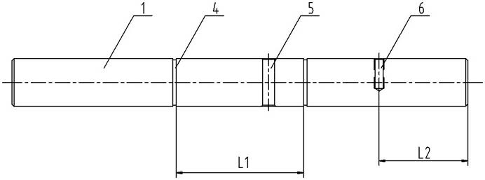
[0033] Embodiment: a kind of massage shaft of this example, as figure 1 , including an intermediate shaft 1 with a length of 129 mm, both ends of the intermediate shaft 1 are connected with an end shaft 2 with a length of 18.5 mm, and a 10 mm threaded head 3 is arranged on the end shaft, and the intermediate shaft, the end shaft, and the threaded head are made of In one piece, the centerlines of the intermediate shaft and the end shafts are on the same plane, and the centerlines of the intermediate shaft and the end shafts are not on the same straight line, and the included angle α between the centerline of the intermediate shaft and the centerlines of the two end shafts is 10°. There are two circlip grooves 4 with a width of 1.35 mm on the intermediate shaft, and a pin hole 5 with a diameter of 5 mm is provided on the intermediate shaft body between the two circlip grooves, and an M4 threaded hole 6 is provided at one end of the intermediate shaft.

[0034] A kind of processi...


PUM


Abstract

The invention discloses a part of a massage chair and a machining method of the part, in particular to a massage shaft used in a massage chair reduction box and a machining method of the massage shaft, mainly solving the technical problems that fatigue cannot be eliminated due to violent and nonuniform massage actions of the traditional massage chair in the prior art and the traditional massage chair has higher requirement for transmission side gaps and otherwise has idle stroke and the like. The massage shaft comprises an intermediate shaft, wherein two end parts of the intermediate shaft are respectively provided with an end shaft in a connecting manner, threaded heads are arranged on the end shafts, center lines of the intermediate shaft and the end shafts are positioned in the same plane but are not positioned on the same line, and included angles of the intermediate shaft and the two end shafts are same. The machining method comprises the steps of: blanking, turning, machining a clamp spring groove, drilling, then aslant fixing the massage shaft by using a clamp, and finally turning the end shafts and the threaded heads.

Description

technical field [0001] The invention relates to parts and processing methods of a massage chair, in particular to a massage shaft used in a reduction box of a massage chair and a processing method thereof. Background technique [0002] Massage chairs have a history of many years, and the most common ones are coin-operated massage chairs provided at airports and hot spring attractions. However, due to technical reasons, the massage action of the old-fashioned massage chair is violent and uneven, which cannot relieve fatigue. Since 2000, the technology of massage chairs has become so sophisticated that manufacturers have started to produce high-tech 3D massage chairs that can gently and skillfully massage the human body. The rapid development of massage chair technology is brought about by the rapid expansion of the market, the intense competition among massage chair manufacturers, and the gradual maturity of the industry. Contents of the invention [0003] The need of the...

Claims


Application Information

Patent Timeline
Patent Type & Authority Applications(China)
IPC IPC(8): A61H1/00
Inventor 江文斌叶茂行
Owner HANGZHOU XINGDA MACHINERY
Learn More