Fuel vapour storage

A fuel vapor and fuel tank technology, which is applied in the directions of adding non-fuel substances to fuel, combining with the fuel supply of internal combustion engines, charging systems, etc., can solve problems such as the exhaustion of fuel vapor capacity.

Inactive Publication Date: 2011-08-17
KAUTEX TEXTRON
View PDF11 Cites 9 Cited by
  • Summary
  • Abstract
  • Description
  • Claims
  • Application Information

AI Technical Summary

Problems solved by technology

As a result, the fuel vapor capacity of ordinary canisters is depleted relatively quickly

Method used


Image

  • Fuel vapour storage
  • Fuel vapour storage
  • Fuel vapour storage

Examples


Embodiment Construction

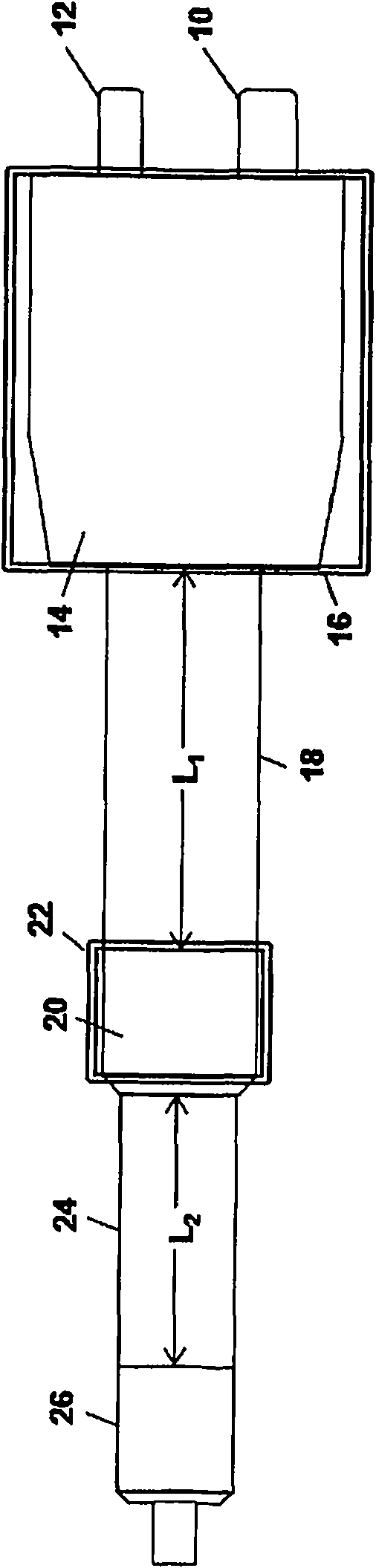
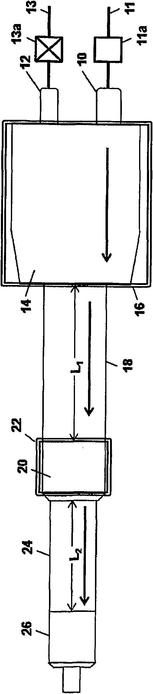
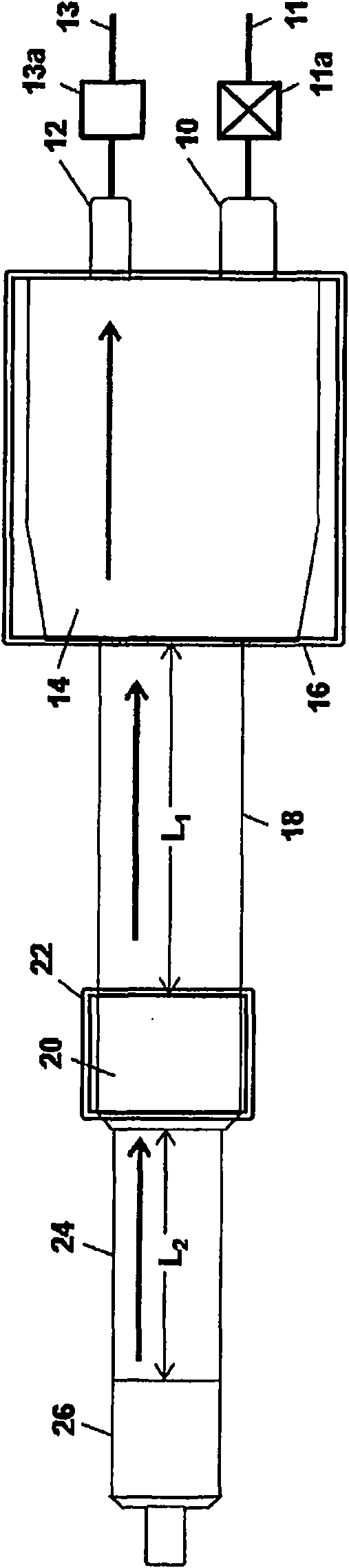
[0025] Embodiments of the present invention provide an absorber tank for controlling emissions from an automotive fuel tank, the tank comprising first and second adsorbent beds and flow channels configured to transfer the The beds are connected in series, wherein the flow path includes a heat exchanger configured to exchange heat between the first adsorbent bed and ambient air, the heat exchanger being internally partitioned to Air is directed in a serpentine path on the outer wall of an adsorbent bed.

[0026] The first adsorbent bed may be configured for end-to-end flow and may have polygonal, elliptical, or cylindrical side walls, the heat exchanger configured to cover more than 50% of the area of ​​the side walls, In a further embodiment more than 75% of the area of ​​the sidewall is covered, and in a still further embodiment more than 90% of the area of ​​the sidewall is covered. The internal partition of the heat exchanger may be configured so that the gas makes two, fo...


PUM


Abstract

A fuel vapour storage canister, e.g. a carbon canister for use in an automobiles evaporative fuel vapour emissions control system is described. The canister comprises a housing defining an inner wall and an outer wall; a first fuel vapour storage compartment arranged within a volume defined by the inner wall; and a second fuel vapour storage compartment in fluid communication with the first vapour storage compartment via an air-flow channel, wherein the air-flow channel includes a section arranged to pass between the inner and outer walls of the housing and to provide a heat-exchange function. Thus air cooled by endothermic desorption in the second fuel vapour compartment during canister purging may be warmed by the ambient air (or other thermal mass) surrounding the outer wall before it reaches the first fuel vapour compartment, thus providing for more efficient desorption in the first fuel vapour compartment. Likewise, air heated by exothermic absorption in the first fuel vapour compartment during canister loading may be cooled by the ambient air before reaching the second fuel vapour compartment, thus providing for more efficient absorption in the second fuel vapour compartment.

Description

technical field [0001] The present invention relates to reducing evaporative emissions from automobiles, and more particularly to fuel vapor storage tanks provided for fitting with motor vehicles for this purpose; to motor vehicles having such tanks fitted thereto; and to utilizing such tanks A method of controlling fuel vapor emissions from a vehicle fuel tank. The present invention is also described in UK Patent Application No. 0817315.5 filed 22 September 2008, the entire disclosure of which is incorporated herein by reference. Background technique [0002] Motor vehicle fuels, such as gasoline used in automobiles, are relatively volatile, and it is generally desirable to reduce the amount of fuel vapor that escapes into the atmosphere. Indeed, in many countries, laws exist that limit the amount of fuel vapor that can be released from a motor vehicle. Evaporative fuel emissions are primarily due to draining from vehicle fuel tanks. Because fuel is volatile, the air wit...

Claims


Application Information

Patent Timeline
Patent Type & Authority Applications(China)
IPC IPC(8): F02M25/08
CPCF02M25/0854B60K15/035F02M25/08
Inventor T·T·黄
Owner KAUTEX TEXTRON
Why Eureka
Try Eureka