Pulse backflushing cleaning device and its gas ejector and filter device

A technology of pulse backflushing and dust removal device, which is applied in the fields of dispersed particle filtration, transportation and packaging, chemical instruments and methods, etc. It can solve the problems of more severe vibration of filter tubes, impact force of filter tubes, bridging of dust layers, etc., to achieve Uniform and thorough dust removal, increased air intake rate, and reduced vibration

Inactive Publication Date: 2018-10-16
HENAN POLYTECHNIC UNIV
View PDF3 Cites 0 Cited by
  • Summary
  • Abstract
  • Description
  • Claims
  • Application Information

AI Technical Summary

Problems solved by technology

[0008] First of all, in order to effectively clean the filter tube at the edge position inside the ejector, in actual operation, it often needs a back-flush cleaning pressure that is about twice the operating pressure of the filter. The high pressure of back blowing and cleaning will cause the filter tube to be subjected to a great impact force, which will easily cause the filter tube to vibrate during this process. The higher the back blowing and cleaning pressure, the more violent the vibration of the filter tube. The filter tube is damaged or even broken due to thermal shock fatigue
[0009] In addition, during pulse blowback, since the high-pressure and high-speed blowback airflow will inject clean gas from around the opening end of the filter tube into the inside of the filter tube, it is easy to form a "negative pressure zone" near the open end. There is dust outside the filter tube being entrained to the surface of the filter tube in this area. If the dust cannot be completely cleaned, it will cause the dust layer between the filter tubes to bridge, which will easily cause the filter tube to fail

Method used


Image

  • Pulse backflushing cleaning device and its gas ejector and filter device
  • Pulse backflushing cleaning device and its gas ejector and filter device
  • Pulse backflushing cleaning device and its gas ejector and filter device

Examples


Embodiment Construction

[0025] In order to have a clearer understanding of the technical features, purposes and effects of the present invention, the specific implementation manners of the present invention will now be described in detail with reference to the accompanying drawings.

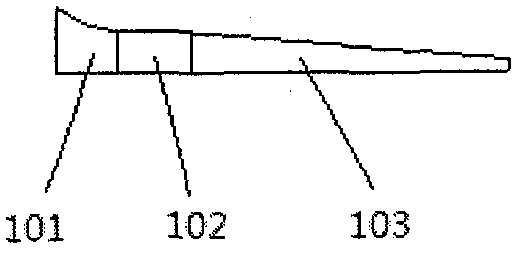
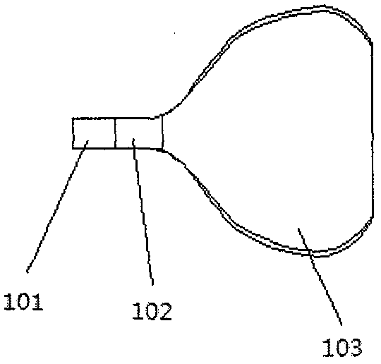
[0026] Figure 1a with 1b A gas ejector of a pulse back-blowing soot cleaning device provided by an embodiment of the present invention. The gas ejector includes an ejector body, and the ejector body includes an inlet portion 101, a neck portion 102 and an arched portion 103 connected to each other in sequence, wherein the longitudinal direction of the inlet portion 101, the neck portion 102, and the arched portion 103 The width of the section ( Figure 1b The vertical direction shown is the width direction of the gas ejector) first increases and then decreases, and the height ( Figure 1a The vertical direction shown is the height direction of the gas ejector) gradually decreasing.

[0027] In this way, from the inle...


PUM


Abstract

The invention provides a pulse back-blowing dust cleaning device, a gas ejector and a filter device thereof. The gas ejector used by the pulse back-blowing soot cleaning device and the filter device includes an ejector body, and the ejector body includes an inlet part, a neck and an arched part connected to each other in sequence, and the inlet part, the neck The width of the longitudinal section of the portion and the arched portion first increases and then decreases, and the height gradually decreases, and the gas ejector is arranged transversely to the filter tube of the filter device. By improving the shape of the gas ejector and its setting in the pulse back-blowing soot cleaning device, the filter tubes corresponding to the gas ejector can be blown back more uniformly, improving the efficiency of blowing into the gas ejector. The airflow distribution condition makes the filter tube get even and thorough cleaning. In this way, the pressure of back blowing and dust cleaning can be reduced, the vibration of the filter tube can be reduced, and the risk of thermal shock and fatigue fracture can be reduced; the second is that it can avoid the bridging of the dust layer between the filter tubes and avoid the failure of the filter tube.

Description

technical field [0001] The invention belongs to the technical field of gas-solid separation, and relates to a filter device, in particular to a pulse back-blowing soot cleaning device in the filter device and a gas ejector thereof. Background technique [0002] With the deterioration of air quality, more and more attention has been paid to the development of filter materials for high-temperature exhaust gas filtration and emission. In recent years, a large amount of high-temperature industrial waste gas has caused serious pollution to the atmospheric environment. Topics such as "air quality", "smog", and "PM2.5" have rapidly heated up and become hot issues of global concern. Therefore, the development and optimization of high temperature dust removal technology is extremely important. [0003] In chemical industry, petroleum, metallurgy, electric power and other industries, high temperature dusty gas is often produced. Since these different processes need to recover energy...

Claims


Application Information

Patent Timeline
Patent Type & Authority Patents(China)
IPC IPC(8): B01D46/42B01D46/24
CPCB01D46/24B01D46/42B01D46/72B01D46/71
Inventor 李海霞白雪王发辉张明军朱崎峰李宾
Owner HENAN POLYTECHNIC UNIV
Why Eureka
Try Eureka