
Combine harvester grain cleaning system

a technology of grain cleaning system and harvester, which is applied in the field of combinator harvester, can solve the problems of affecting affecting the direction of harvester, and affecting the direction of forward flow air, so as to improve the performance of the cleaning system and reduce backpressure

Active Publication Date: 2019-06-18
AGCO INT GMBH
View PDF32 Cites 6 Cited by
  • Summary
  • Abstract
  • Description
  • Claims
  • Application Information

AI Technical Summary

Benefits of technology

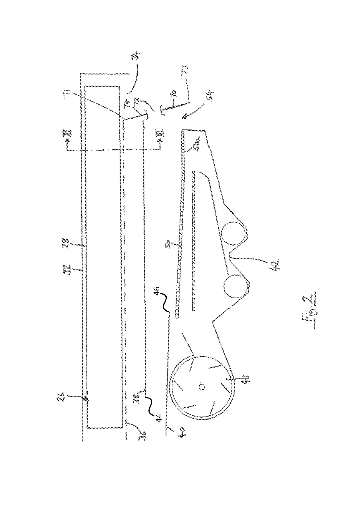
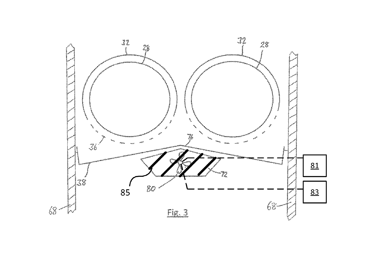
[0008]The aperture in the rear wall of the cleaning shoe serves to provide means of air relief for an improved distribution of the cleaning airstream in the cleaning shoe.
[0010]The ‘backpressure’ exerted on the cleaning airstream is thought to be caused by the restricted outlet at the rear of the cleaning shoe. The trend for inclusion of chaff spreaders and straw choppers in the area immediately behind the cleaning shoe serves only to compound this problem. By providing an aperture in the rear wall of the cleaning shoe, the backpressure is reduced thus allowing a freer flow of air from fore to aft, ultimately improving the performance of the cleaning system.
[0013]The aperture is preferably as high as possible in the rear wall, proximate to the underside of the return pan if provided. Therefore, the lifting and conveying of the MOG is enhanced.
[0015]The combine harvester preferably further comprises an auxiliary fan located inside the aperture, the auxiliary fan being operable to positively draw air away from the cleaning system. By providing a dedicated fan to actively draw air through the aperture the air distribution in the cleaning shoe is not only improved, but is also more controllable. In a preferred arrangement the speed of the auxiliary fan is controlled in conjunction with the main cleaning fan speed.

Problems solved by technology

However, it has been observed that the air distribution inside the cleaning shoe becomes more disrupted with such high fan speeds, sometimes even resulting in regions of forward flow air which is detrimental to the overall grain cleaning system which relies on a generally rearward conveyance of the MOG.

Method used


Image

  • Combine harvester grain cleaning system
  • Combine harvester grain cleaning system
  • Combine harvester grain cleaning system

Examples


Embodiment Construction

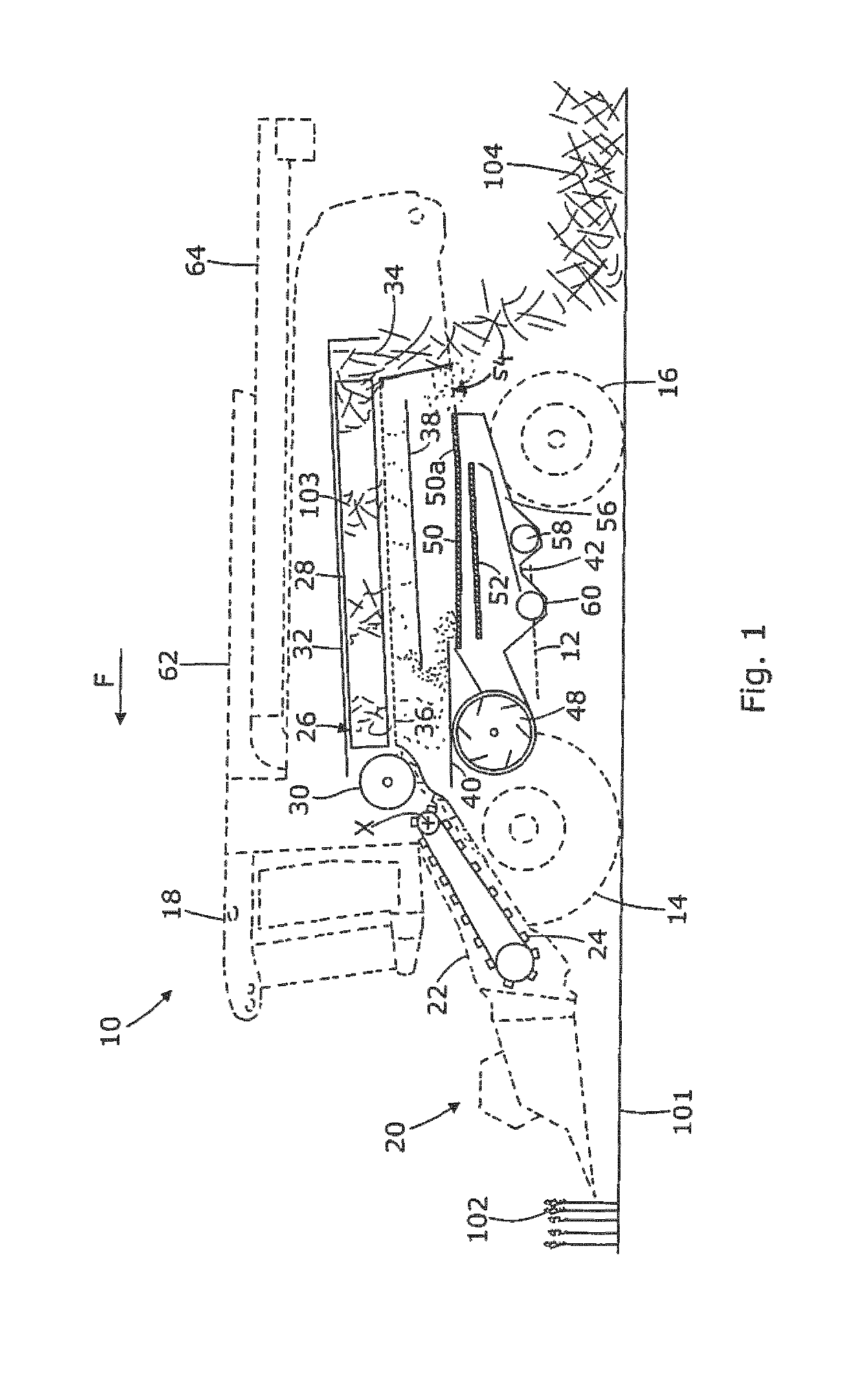
[0021]An embodiment of the invention will now be described with reference to the drawings. Relative terms such as forward, rearward, transverse, lateral, longitudinal and sideways will be made with reference to the normal forward direction of travel of the combine 10 and indicated by arrow F. The terms vertical and horizontal will be made with reference to the level ground 101 upon which the combine 10 is disposed. In other words the Cartesian axes of ‘longitudinal’, ‘transverse’, and ‘vertical’ are made in relation to the frame 12 of combine 10 and are not affected by any slope in the ground. The terms “upstream” and “downstream” are made with reference of the general direction of crop flow along the material conveyance systems described.

[0022]FIG. 1 illustrates in schematic form the main components of the crop processing system of a combine harvester 10 and will be used to explain the flow of material below. The crop processing system is shown in solid lines whilst the outline pro...


PUM


Abstract

A grain cleaning system in a combine harvester including a pair of side walls, a rear wall that extends between the side walls, a sieve that oscillates in a fore-and-aft path between the side walls, a fan unit for generating a cleaning airstream, and an outlet for discharging residue from a grain-cleaning process. The outlet is framed in part by a lower edge of the rear wall. An aperture is provided in the rear wall to provide air relief to enhance the fore-to-aft flow of the cleaning airstream. Optionally, an auxiliary fan may drive air through the aperture.

Description

BACKGROUND OF THE INVENTIONField of Invention[0001]The invention relates to combine harvesters and particularly to grain cleaning systems installed thereon, the cleaning system having one or more sieves which oscillate to clean grain, and a fan unit which generates a cleaning airstream.Description of Related Art[0002]Self-propelled combine harvesters have been used by farmers since the early twentieth century to harvest grain crops from fields. Since then the basic architecture of the crop processing system employed has not changed significantly and is well known.[0003]A cutting header cuts and gathers a standing crop which is conveyed generally rearwardly to crop processing apparatus. On-board threshing and separating apparatus serve to thresh the stream of cut crop material and separate the grain or seeds from the straw. The straw material is typically conveyed to the rear of the separating apparatus from where it is discharged to the ground whilst the grain and material other tha...

Claims


Application Information

Patent Timeline
Patent Type & Authority Patents(United States)
IPC IPC(8): A01F12/44
CPCA01F12/444A01F12/44A01F12/442A01F12/446
Inventor BILDE, MORTEN LETH
Owner AGCO INT GMBH
Learn More