Efficient mixed-flow pump with self-cooled submersible motor

A submersible motor and mixed-flow pump technology, which is applied to the components, pumps, and pumping devices of elastic fluid pumping devices, can solve the situation where the motor cannot be submerged, the large hydraulic loss of the motor wellbore tee, the guide vane, etc. Problems such as large diffusion loss, to achieve the effect of reducing shaft length, low flow channel loss, and small diffusion loss

Pending Publication Date: 2018-11-13
合肥凯泉电机电泵有限公司
View PDF10 Cites 0 Cited by
  • Summary
  • Abstract
  • Description
  • Claims
  • Application Information

AI Technical Summary

Problems solved by technology

[0003] However, traditional submersible mixed-flow pumps are generally installed by wellbore suspension or concrete prefabricated wellbore; traditional dry-type mixed-flow pumps are generally installed by double foundations; the installation and maintenance of the pump requires the operation of the whole pump, which is inconvenient
[0004] In addition, the traditional submersible mixed-flow pump uses space guide vanes, and its guide vane has a large diffusion loss; when the wellbore is suspended or the concrete prefabricated wellbore is installed, the water flow is discharged through the motor and the wellbore tee, and the motor and the wellbore tee exist Large hydraulic loss, its efficiency is generally much lower than that of dry mixed flow pumps
On the other hand, although the efficiency of the dry mixed flow pump is very high, its application is limited, and it cannot be applied to the occasion where the motor may be submerged

Method used


Image

  • Efficient mixed-flow pump with self-cooled submersible motor
  • Efficient mixed-flow pump with self-cooled submersible motor

Examples


Embodiment Construction

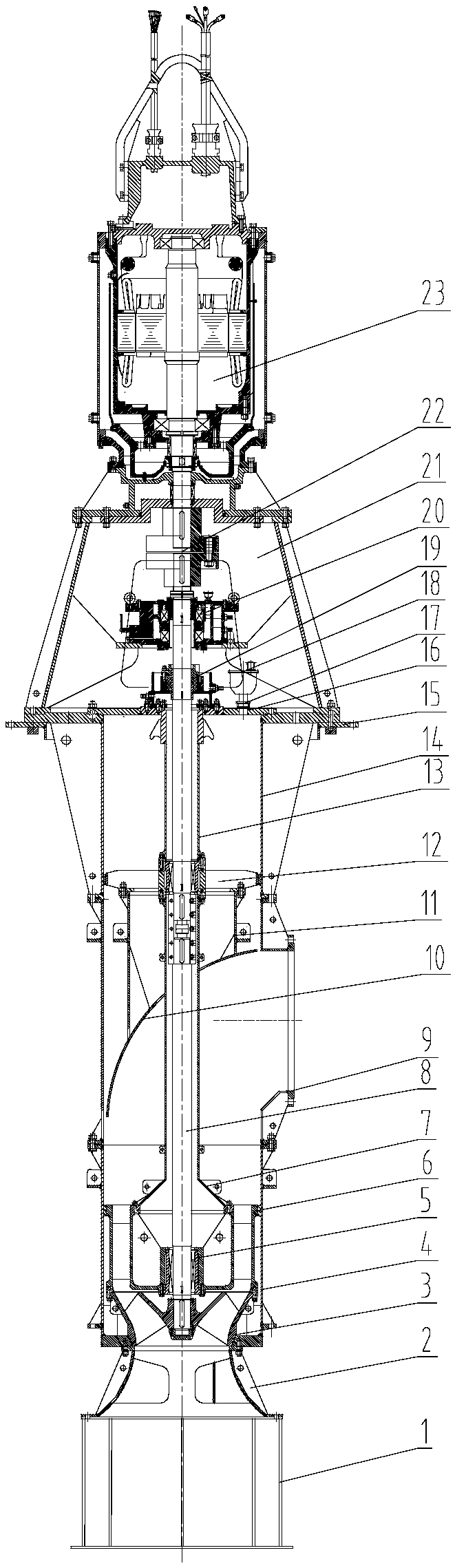
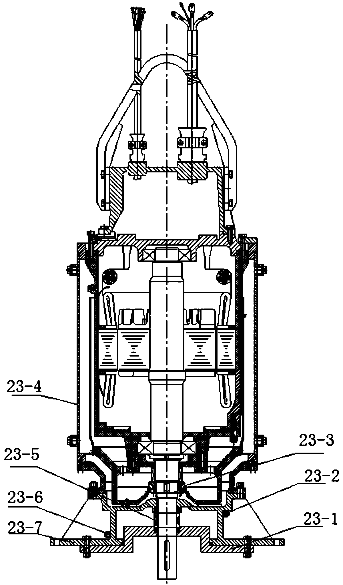
[0026] See attached picture.

[0027] A high-efficiency mixed-flow pump with a self-cooling submersible motor, which adopts a core-pulling structure, and includes a cylinder and a core. The cylinder includes a pump seat 14 composed of long pipes 4. One of the pump seats 14 The side is connected to the elbow 9 through the inner connecting pipe 10 and the deflector 11. The bottom end of the pump seat 14 is equipped with a water inlet bell mouth 2, and the bottom end of the water inlet bell mouth 2 is installed with a suction net cover 1. The core is located in the cylinder, and includes a rotor part 8, the bottom end of the rotor part 8 is equipped with a guide vane body 6 through a bearing 5, and a runner chamber 3 is installed at the bottom end of the guide vane body 6. The upper end of the vane body 6 is equipped with a conical tube 7 sleeved on the rotor part 8, the upper end of the conical tube 7 is provided with an inner protective tube 13 matched with it, and the upper en...


PUM


Abstract

The invention discloses an efficient mixed-flow pump with a self-cooled submersible motor. The efficient mixed-flow pump of a core-pulling structure comprises a barrel body and a core body, wherein the barrel body comprises a pump seat composed of a long pipe, one side of the pump seat is connected to a bend pipe, a water inlet bell mouth is mounted at the bottom end of the pump seat, a suction mesh enclosure is mounted at the bottom end of the water inlet bell moth, the core body is located in the barrel and comprises a rotor part, a guide vane body is mounted at the bottom end of the rotor through a bearing, a rotating wheel chamber is mounted at the bottom end of the guide vane body, a taper pipe mounted on the rotor part in a sleeving mode is mounted at the upper end of the guide vanebody, an inner protecting tube matched with the taper pipe is arranged on the upper end part of the taper pipe, a pump cover is mounted at the upper end of the pump seat, a motor part is mounted on the pump cover, and the motor part is mounted in a cooling sleeve. The efficient mixed-flow pump disclosed by the invention is reasonable in structural design and convenient to mount and maintain, and cools the motor automatically, so that the application range of the motor is wider. The efficient mixed-flow pump is good in stability. Part of parts is designed in a sectional manner, so that the height of a plant is reduced, and the investment is saved.

Description

Technical field: [0001] The invention relates to the field of pumps, and mainly relates to a high-efficiency mixed-flow pump with a self-cooling submersible motor. Background technique: [0002] Mixed-flow pumps are mainly used in urban water supply, urban sewage drainage systems, sewage treatment projects, drainage irrigation, etc.; they have the advantages of large flow, medium and low head, good anti-cavitation performance, and adapt to occasions with large water level changes. [0003] However, traditional submersible mixed-flow pumps are generally installed by wellbore suspension or concrete prefabricated wellbore; traditional dry-type mixed-flow pumps are generally installed by double foundations; the installation and maintenance of water pumps require the operation of the whole pump, which is inconvenient. [0004] In addition, the traditional submersible mixed-flow pump uses space guide vanes, and its guide vane has a large diffusion loss; when the wellbore is suspen...

Claims


Application Information

Patent Timeline
Patent Type & Authority Applications(China)
IPC IPC(8): F04D13/08F04D29/40F04D29/58F04D29/18F04D29/00
CPCF04D13/08F04D29/007F04D29/18F04D29/406F04D29/5806F04D29/586
Inventor 王俊华蔡皖锋王玉心
Owner 合肥凯泉电机电泵有限公司
Why Eureka
Try Eureka