Vehicle with one flow influencing element and method for influencing an aerodynamic drag of a vehicle

An air resistance and vehicle technology, applied in the field of vehicles, can solve problems such as consumption and affecting the appearance of vehicles

Inactive Publication Date: 2011-08-24
GM GLOBAL TECH OPERATIONS LLC
View PDF6 Cites 7 Cited by
  • Summary
  • Abstract
  • Description
  • Claims
  • Application Information

AI Technical Summary

Problems solved by technology

[0003] Although such flow-influencing elements are suitable for reducing the air resistance of the vehicle, they are complex to install on the vehicle and also affect the appearance of the vehicle

Method used


Image

  • Vehicle with one flow influencing element and method for influencing an aerodynamic drag of a vehicle
  • Vehicle with one flow influencing element and method for influencing an aerodynamic drag of a vehicle
  • Vehicle with one flow influencing element and method for influencing an aerodynamic drag of a vehicle

Examples


Embodiment Construction

[0027] Identical parts are provided with the same reference numerals in all figures.

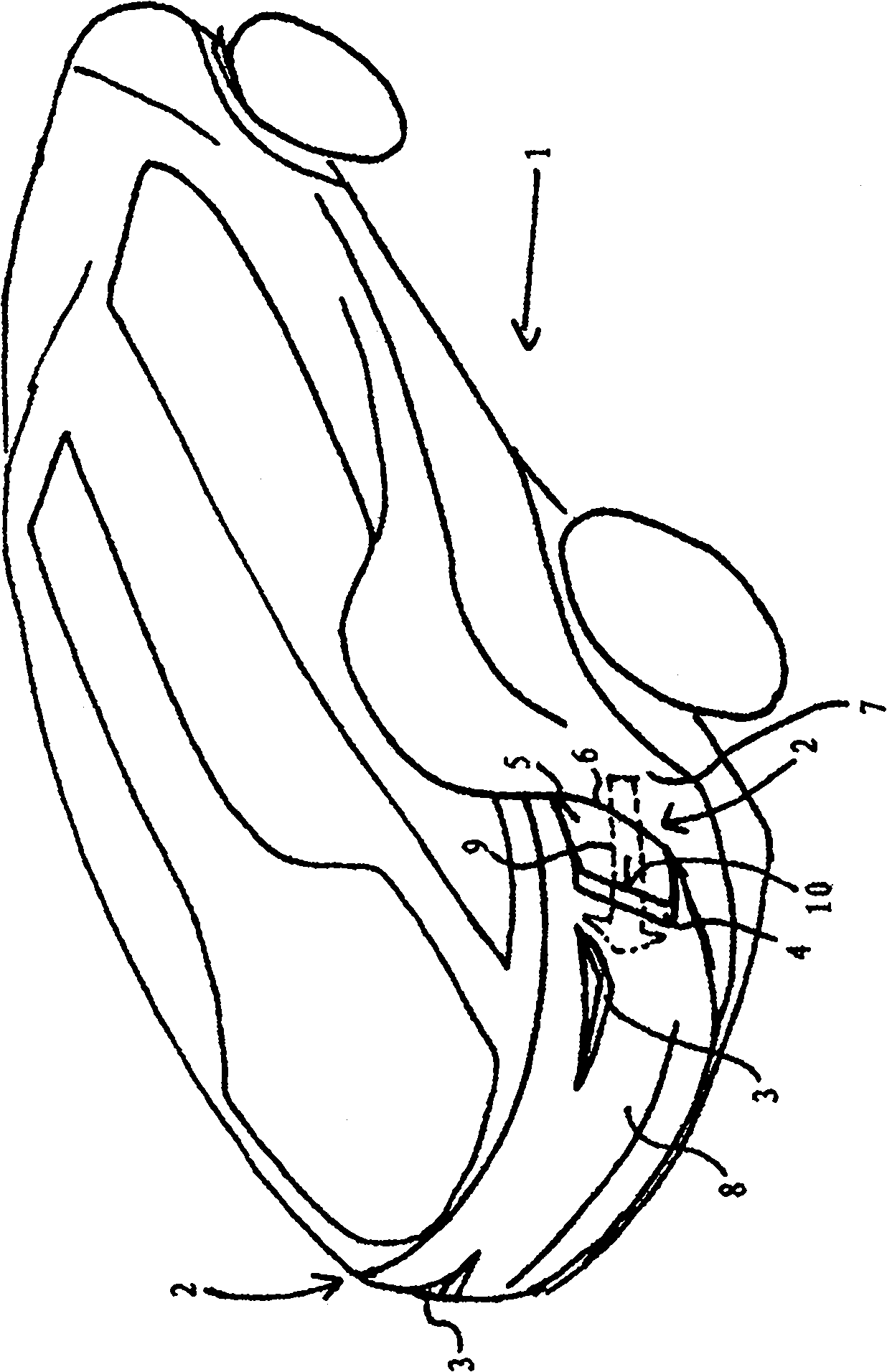
[0028] according to figure 1 The vehicle 1 has a rounded shape overall and in particular in its rear region 8 . Flow-influencing elements 5 (for example spoilers) with flow-separating edges 10 are arranged in the left and right side rear regions 2 in the region in front of the taillights 3 .

[0029] For this purpose, a recess 4 is arranged in the lateral end region 2 on each side, in which recess 4 the flow influencing element 5 can slide.

[0030] The flow influencing element 5 is configured as a fin which can slide parallel to the direction of the vehicle skin indicated by the arrow 9 . A slot 6 is provided in each case for receiving the flow influencing element 5 . The flow-influencing element 5 accommodated in the slot 6 is completely or partially covered by the body element 7 .

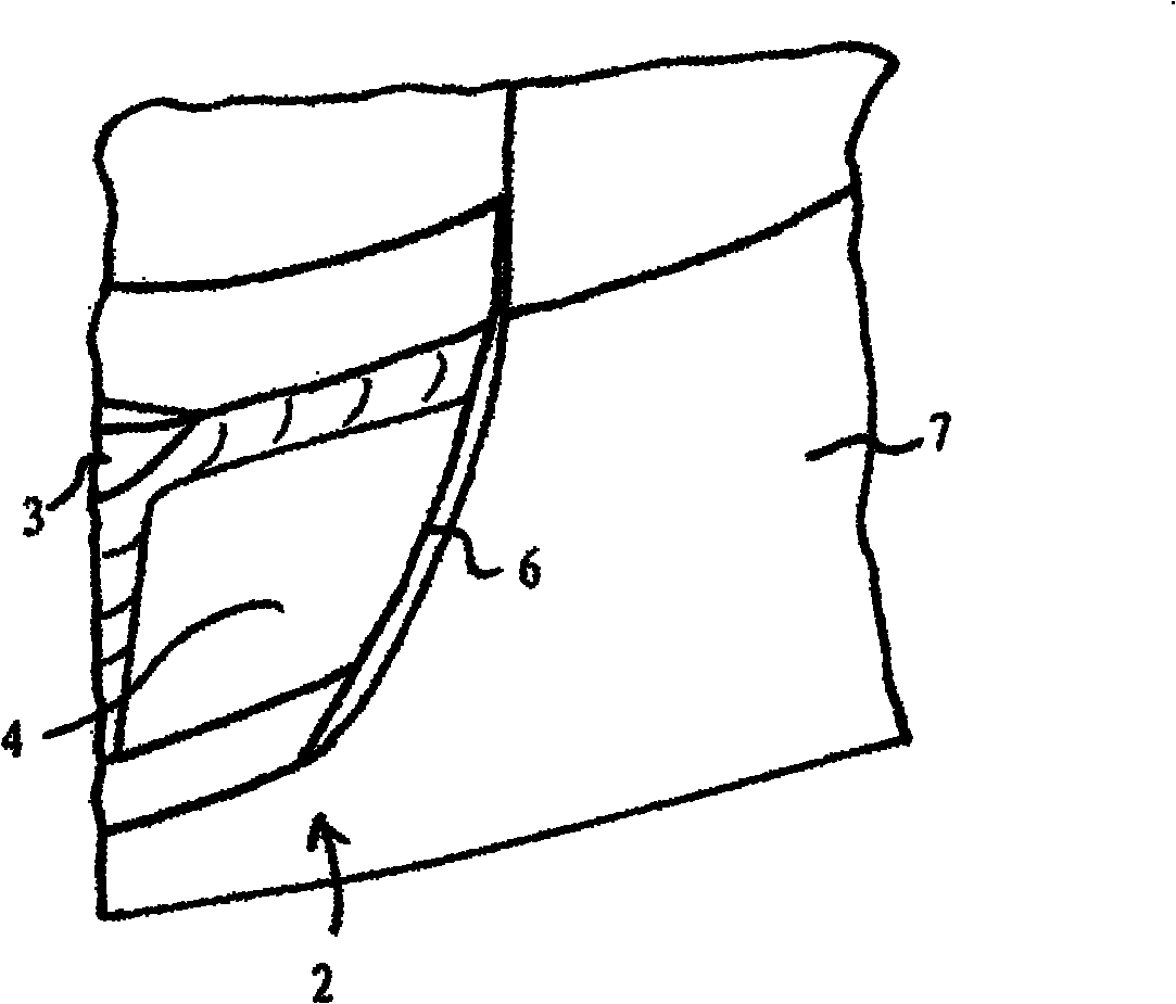
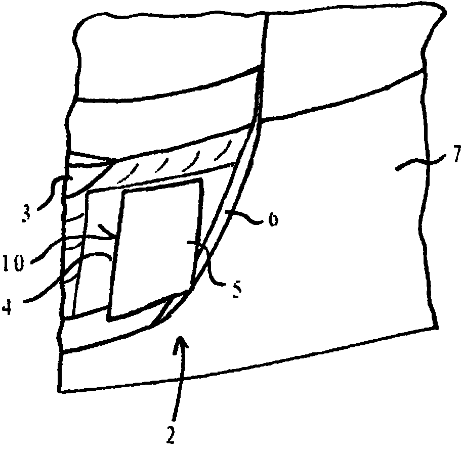
[0031] figure 2 Schematically shows a push button with the flow influencing element 5 in the first po...


PUM


Abstract

A vehicle includes, but is not limited to at least one flow influencing element with a spoiler edge arranged in a lateral rear region of the vehicle. The flow influencing element has a first position, in which the spoiler edge is substantially concealed by a body element and a second position, in which the spoiler edge is substantially exposed.

Description

technical field [0001] The invention relates to a vehicle having at least one flow-influencing element with an airflow separation edge arranged in the rear region of the vehicle side. The invention also relates to a method for influencing the air resistance of a vehicle. Background technique [0002] From DE 199 12 140 C2 a flow-influencing element is known for reducing the air resistance of a vehicle, which can be arranged, for example, in the rear region and moves periodically so that time-dependent disturbances can be introduced in a defined manner Against the wind. [0003] Although such flow influencing elements are suitable for reducing the air resistance of the vehicle, they are complex to install on the vehicle and also affect the appearance of the vehicle. While technical aspects are important when designing vehicle skin and vehicle contours, aesthetic considerations also play an important role. For example, today rounder and smoother contours are trendier and mo...

Claims


Application Information

Patent Timeline
Patent Type & Authority Applications(China)
IPC IPC(8): B62D35/00
CPCB62D35/008Y02T10/82B62D35/007B62D37/02
Inventor 波利斯.伊尔斯波利斯.雅各布尼古拉斯.克鲁斯伯特兰德.巴赫乌尔里克.鲍尔
Owner GM GLOBAL TECH OPERATIONS LLC
Why Eureka
Try Eureka