Wallboard connection column and wall body for combined house

A technology for combining houses and connecting columns, applied in the direction of columns, walls, pier columns, etc., can solve the problems of low construction difficulty and high work efficiency, and achieve the effect of solving the problem of shrinkage joints, convenient house decoration, and firm connections

Inactive Publication Date: 2011-08-31
广州益群板业有限公司
View PDF9 Cites 8 Cited by
  • Summary
  • Abstract
  • Description
  • Claims
  • Application Information

AI Technical Summary

Problems solved by technology

[0008] The purpose of the present invention is to provide a combined house wall panel connecting column and a combined house connecting wall built using the combined house wall panel connecting column, which can solve the shrinkage problem of the wall joint and can be flexibly used for the separation of venues or the construction of combined houses , low construction difficulty and high work efficiency

Method used


Image

  • Wallboard connection column and wall body for combined house
  • Wallboard connection column and wall body for combined house
  • Wallboard connection column and wall body for combined house

Examples


Embodiment 1

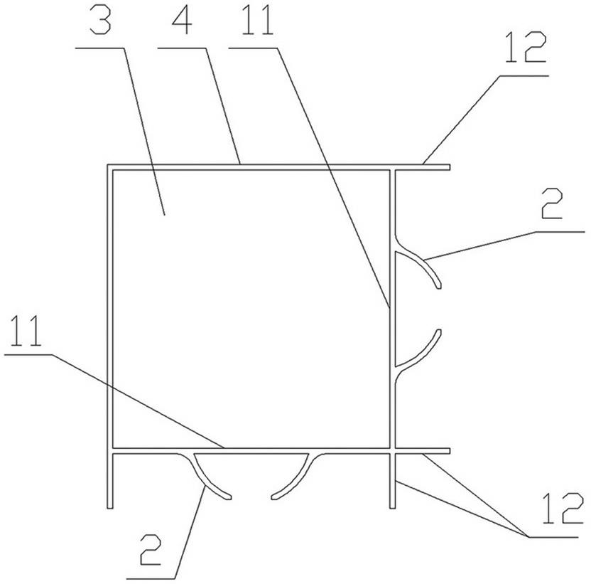
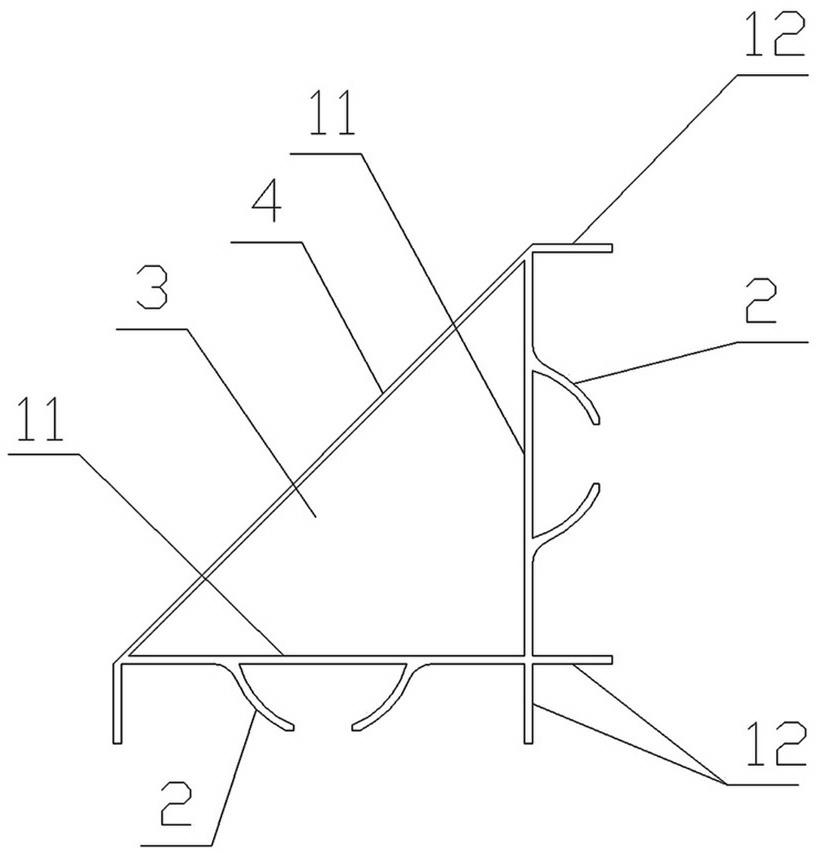
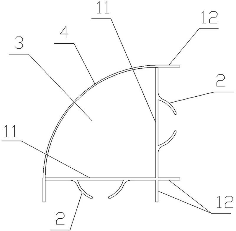
[0036] refer to Figure 1 to Figure 4 , a combined house wall panel connecting column has two U-shaped parts, the U-shaped part has a bottom 11 and a side part 12 and is formed by it to fit a rectangular groove at the end of the wall panel, and a bottom of the two U-shaped parts The 11 ends are vertically intersected, and the two sides of the connecting edge 4 are intersected with the other end of the bottom 11 of the two U-shaped parts. The connecting edge 4 can be designed as a straight plate (such as figure 2 ), rectangular plate shape (such as figure 1 ), curved plate shape (such as image 3 ) or irregular shape (such as Figure 4 ); connect the edge sealing 4 and the bottom 11 of the two U-shaped parts to form a pipe structure with a pipe 3 inside, and the middle section of the bottom 11 in the rectangular groove of each U-shaped part is provided with a snap-flap 2 , and the snap-flap 2 It is T-shaped, Π-shaped, octagonal or double-L-shaped. This embodiment only enum...

Embodiment 2

[0040] refer to Figure 6 , a combined house wall panel connecting column, has two U-shaped parts, the U-shaped part has a bottom 11 and a side part 12 and is formed by it to fit a rectangular groove at the end of the wall panel, and the two bottoms of the two U-shaped parts 11 are parallel and the directions of the notches of the rectangular grooves are opposite. The two ends of the bottom 11 of the two U-shaped parts are connected by the connecting edge 4 to form a pipe structure with a pipe 3 inside. The middle section of the bottom 11 of the rectangular groove of each U-shaped part There is a card wing plate 2 on the top, and the card wing plate 2 is T-shaped, Π-shaped, octagonal or double L-shaped. Present embodiment only enumerates eight shapes.

[0041] combined reference Figure 11 , using the wall of the linear composite house built in this embodiment, the method is the same as in Embodiment 1.

Embodiment 3

[0043] refer to Figure 7 , Figure 9 and Figure 10 , the present embodiment, as an optimization of embodiment 2, differs from embodiment 2 in that: the middle section of the bottom 11 of the two U-shaped parts is a circular arc segment, and the snap-wing plate 2 provided on the middle section of the bottom 11 of the U-shaped part has an eight-shaped ( Such as Figure 7 ), Π shape (such as Figure 9 ) and double L-shape (such as Figure 10 ).

[0044] The method of using the linear composite house wall built in this embodiment is the same as that in Embodiment 1.

[0045] Compared with embodiment 2, the space of the bonding area 7 in this embodiment is slightly smaller, which can reduce the amount of glue; the space of the pipeline 3 is larger, which is beneficial to the laying of electric wires or water pipes.


PUM


Abstract

The invention relates to a wall body for a combined house, and provides a wallboard connection column for the combined house. The connection column is provided with at least one U-shaped part; each U-shaped part is provided with a bottom and an edge, and the bottom and the edge form a rectangular groove which is adaptive to the end part of each wallboard; T-shaped, n-shaped or dual L-shaped clamping wing plates or clamping wing plates which are in a shape like a figure eight are on middle sections of the internal bottoms of the rectangular grooves of the connection column, so the connection column and the wallboards are connected to form the wall body for the combined house; concave grooves are formed at both side ends of each wallboard; the end part of each wallboard is positioned in the rectangular grooves of the connection column; the groove bottoms of the concave grooves of the wallboards and the groove bottoms of the rectangular grooves of the connection column form bonding areas; the clamping wing plates of the connection column are positioned in the bonding areas; and the wallboards and the connection column are fixed by glue in the bonding areas. The wallboard connection column has the substantial characteristics and obvious advantages that: 1, the right-angle, linear, T-shaped or cross-shaped wall bodies for the combined house is convenient to construct; 2, the joints of the wall bodies are firm and attractive in appearance, and the problem of contraction gaps at the joints of the wall bodies is solved; and 3, water pipes or electric wires, network wires and the like can be distributed pipelines reserved by the connection column so as to bring convenience to interior decoration.

Description

technical field [0001] The invention relates to building materials, in particular to composite building walls and connectors. Background technique [0002] When people build simple houses or indoor compartments, they often use wall panels to build the walls of combined houses. There are corresponding mortises and mortises, the shape of the mortise and the corresponding mortise is long arc, triangle or square, the mortise of one wallboard is inserted into the mortise of the other wallboard, and the tenon and mortise Apply adhesive to the joints to connect the two wall panels. [0003] There are following problems in the use process of building the connecting wall of the combined house in this way: [0004] 1. The positioning between the wall panels is difficult, it is easy to dislocate, the installation is difficult, and the construction speed is slow; [0005] 2. The wall panels are simply bonded by the wall panel adhesive, which has poor firmness, and it is easy to defor...

Claims


Application Information

Patent Timeline
Patent Type & Authority Applications(China)
IPC IPC(8): E04C3/30E04B2/74E04B2/82
Inventor 朱志镳刘毅
Owner 广州益群板业有限公司
Why Eureka
Try Eureka