Threading tube coupler of wind generating set

A technology for wind turbines and threading pipes, which is applied to wind turbine components, wind turbines, couplings, etc. There are no problems such as self-aligning effect, so as to achieve good self-aligning effect, prevent twisting, and facilitate installation and disassembly.

Active Publication Date: 2013-07-03
JIANGSU NEW UNITED HEAVY IND SCI & TECH +1
View PDF7 Cites 0 Cited by
  • Summary
  • Abstract
  • Description
  • Claims
  • Application Information

AI Technical Summary

Problems solved by technology

In existing wind turbines, some threading pipe couplings use standard plum-shaped couplings, but the plum-shaped couplings are not conducive to the disassembly of the couplings for the input shaft of the generator and the output shaft of the gearbox.
In addition, there is a deviation in the center of the input shaft of the generator and the output shaft of the gearbox during installation, which leads to a deviation in the center of the threading pipe and the threading pipe. The threading pipe coupling in the prior art has no centering effect

Method used


Image

  • Threading tube coupler of wind generating set
  • Threading tube coupler of wind generating set
  • Threading tube coupler of wind generating set

Examples


Embodiment 1

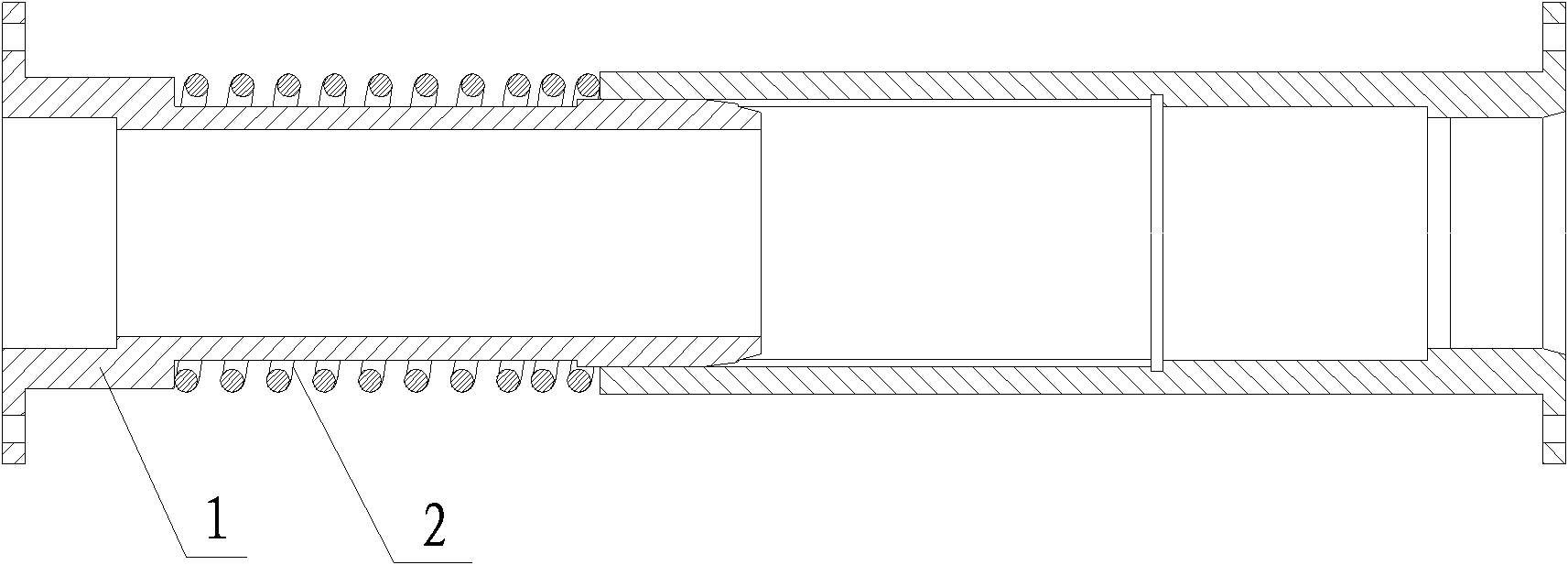
[0020] Embodiment one: if figure 1 figure 2 As shown, a threading pipe coupling for a wind power generating set has a left joint 1, a spring 2, and a right partial joint. Both the left joint 1 and the right partial joint have hollow cavities inside, and the front end of the left joint 1 is connected to the right partial joint. The rear end is connected by clearance fit. The outer circumference of the left joint 1 has a stepped card slot. The spring 2 is installed in the stepped card slot. The blocking surface at the front end of the stepped card slot is lower than the blocking surface at the rear end. On the blocking surface of the rear end of the type card slot, the other end of the spring 2 is against the end face of the rear end of the right part of the joint, a sliding key is provided on the outer circumference of the front end of the left joint 1, and a sliding key is provided on the inner peripheral surface of the right part of the joint. Fitted keyway.

[0021] The i...

Embodiment 2

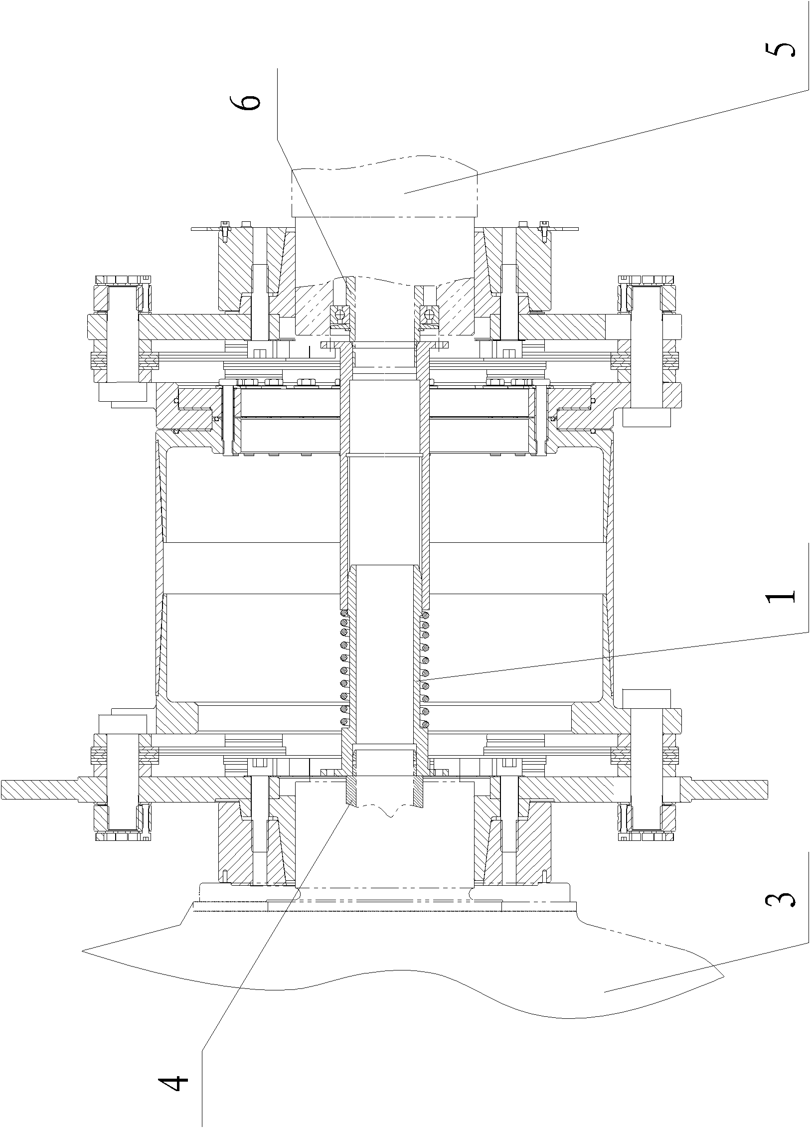
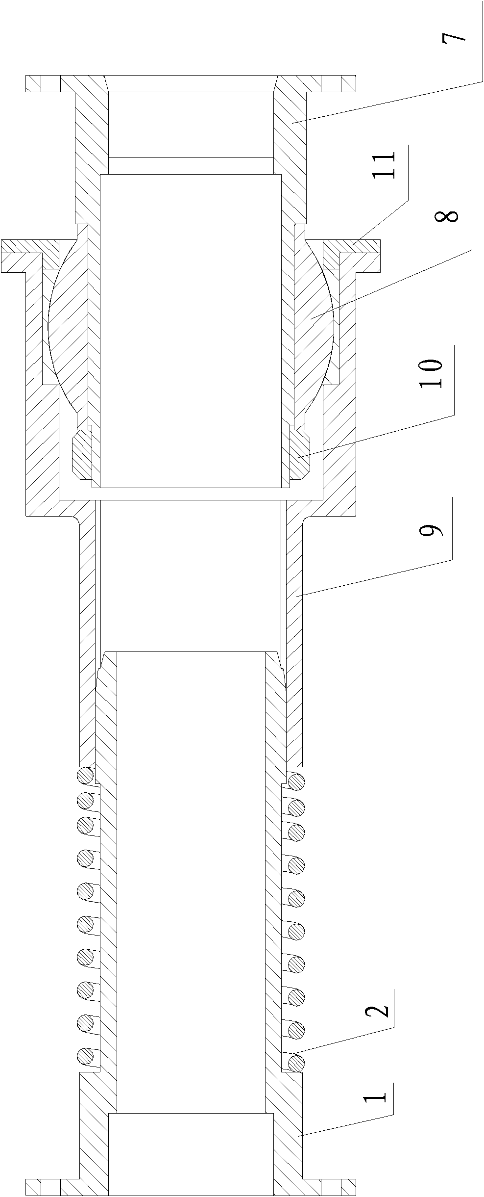
[0023] Embodiment two: if image 3 Figure 4 As shown, a threading pipe coupling of a wind power generating set, the right part of the joint includes a bearing seat 9 and a right end joint 7, and the inside of the right end joint 7 has a sixth cavity connected to the second threading pipe joint 6 of the input shaft of the generator 5 And the seventh cavity for placing the line pipe, the outer circumference of the right end joint 7 has the first step, the second step, and the third step that decrease in turn, and the joint bearing 8 is installed on the second step, and the joint bearing 8 is formed by the nut 10 Locked on the right end joint 7, the front end of the bearing seat 9 has a gland 11, and the gland 11 presses the joint bearing 8.

[0024] Inside the bearing housing 9 there is an eighth cavity for clamping the joint bearing 8, a ninth cavity for placing nuts 10 and wire tubes, and a tenth cavity for clearance fit with the front end of the left joint 1, and the bearin...


PUM


Abstract

The invention relates to a threading tube coupler of a wind generating set, which is provided with a left joint, a spring and a right part joint, wherein the end part of the front end of the left joint is in clearance fit connection with the end part of the rear end of the right part joint; the periphery of the left joint is provided with a stepped clamping groove; the spring is mounted in the stepped clamping groove; a blocking surface at the front end of the stepped clamping groove is lower than that at the rear end of the stepped clamping groove; one end of the spring is pressed against the blocking surface at the rear end of the stepped clamping groove; the other end of the spring is pressed against the end surface of the rear end of the right part joint; the outer periphery of the end part of the front end of the left joint is provided with a sliding key; and the inner peripheral surface of the right part joint is provided with a key slot matched with the sliding key. The threading tube coupler is expandable, so an input shaft of an electric generator and an output shaft of a speed increasing gearbox are convenient to install and disassemble by the coupler. The threading tubecoupler allows a left threading tube and a right threading tube to have certain eccentricity and higher eccentricity.

Description

technical field [0001] The invention relates to the technical field of threading pipe couplings, in particular to a threading pipe coupling of a wind power generating set. Background technique [0002] In the wind power generating set, the electric control cabinet needs to provide power for the pulp change cabinet, and the pulp change cabinet rotates with the hub, and the electric control cabinet is stationary. To prevent twisting of the cables, conduits are required in the drive chain. Such as figure 1 The layout of the threading pipe of the wind power generating set is shown. In this unit, the threading pipe is divided into two sections, one is inside the generator, and the other is inside the gearbox and the main shaft. The function of the threading pipe coupling is to connect the two sections of threading pipe Connect them and keep the two sections of threading pipes synchronized, that is, there is no relative movement. The threading pipe coupling is arranged inside t...

Claims


Application Information

Patent Timeline
Patent Type & Authority Patents(China)
IPC IPC(8): F16D3/06F16D3/20F03D11/04
CPCY02E10/728
Inventor 余晓明张成青杨亚俊张乐平郭立权
Owner JIANGSU NEW UNITED HEAVY IND SCI & TECH
Why Eureka
Try Eureka