
Fluid sensor

A fluid sensor and housing technology, applied in the field of fluid sensors, can solve problems such as oil supply waste and insufficient oil supply, and achieve the effects of preventing waste, simple and easy operation, and realizing flow

Inactive Publication Date: 2011-08-31
BEIJING CMRC SCI & TECH DEV
View PDF7 Cites 4 Cited by
  • Summary
  • Abstract
  • Description
  • Claims
  • Application Information

AI Technical Summary

Problems solved by technology

[0004] For this reason, the technical problem to be solved by the present invention is to provide a fluid sensor capable of quantitatively controlling the passing lubricant, which overcomes the lack of oil supply or waste of oil supply caused by the existing fluid sensor because the flow rate cannot quantitatively control the lubricant. question

Method used


Image

  • Fluid sensor
  • Fluid sensor
  • Fluid sensor

Examples


Embodiment Construction

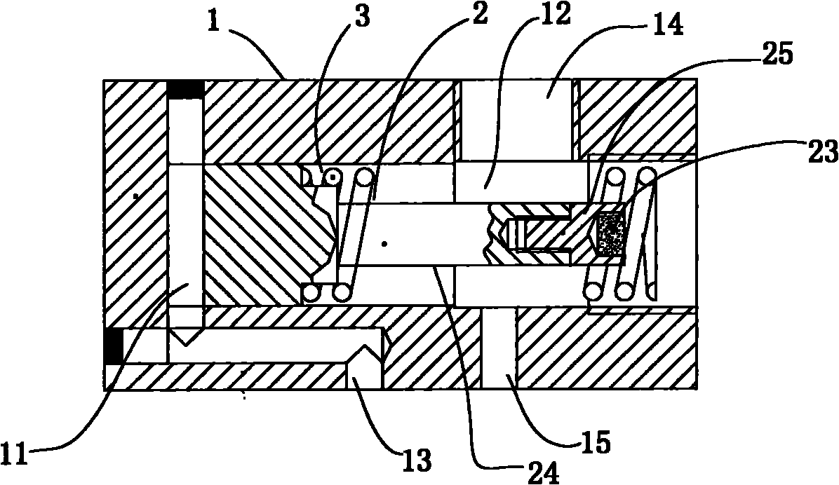
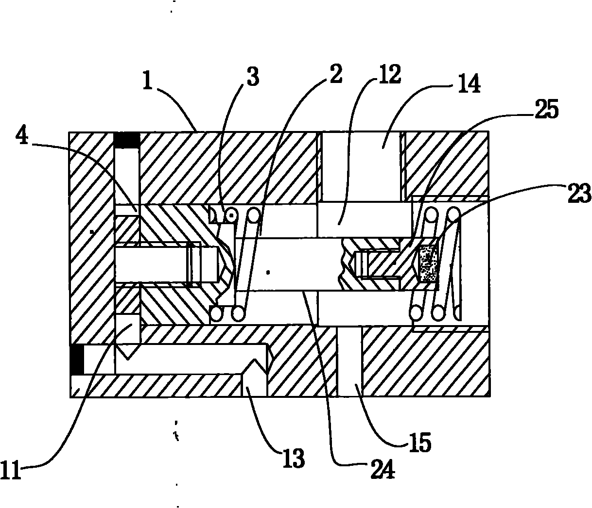
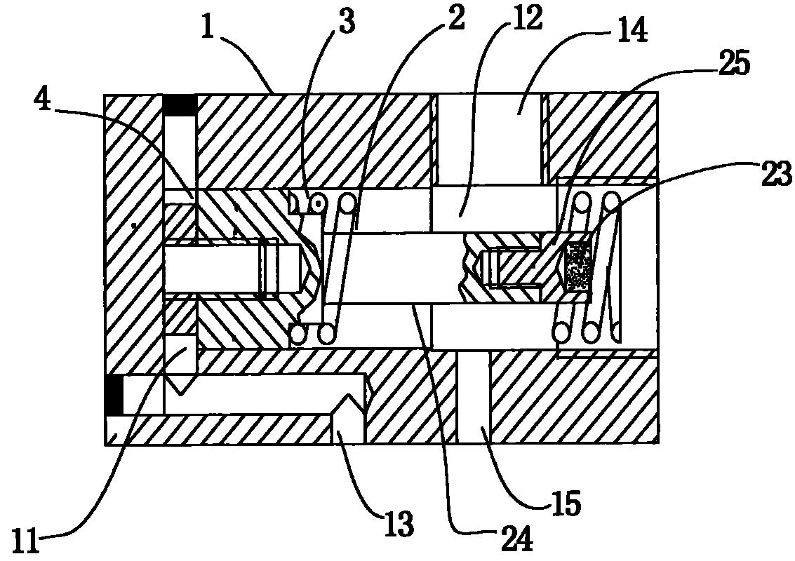
[0028] The structure of the fluid sensor of the present invention is as figure 1 As shown, it includes a housing 1, a piston 2 and a signal transmitter arranged in the housing 1, and the space surrounded by the housing 1 forms a cavity. The piston 2 is slidably disposed in the cavity, and divides the cavity into an inflow cavity 11 and an outflow cavity 12 . A resetting device 3 for resetting the piston 2 is also provided in the outflow chamber 12, an inductive element 23 is provided at an end of the piston 2 close to the signal transmitter, and an end of the housing 1 close to the inductive element 23 is connected to the The sensing element 23 is correspondingly fixed with a signal transmitter (not shown in the figure). The fluid sensor is also provided with a regulating device 4 for regulating the fluid flow.

[0029] The piston 2 of the fluid sensor is provided with a sealing groove, and an o-shaped sealing ring is installed in the sealing groove to prevent leakage. The ...


PUM


Abstract

The invention relates to a fluid sensor which comprises a shell, a signal transmitter, a piston and a resetting device, wherein the piston is slidably arranged in a cavity of the shell and used for dividing the cavity of the shell into an inflow cavity and an outflow cavity; an induction element is arranged at one end of the piston adjacent to the signal transmitter; an inflow opening is arranged on the shell of one side of the inflow cavity; and the shell at one side of the outflow cavity is provided with an outflow opening and a flow supplementary opening as well as a regulating device used for regulating the maximum volume of the outflow cavity. The fluid sensor solves the technical problem of insufficient or waste oil feeding amount when the oil feeding amount of an oil feeder can not be accurately controlled by the traditional fluid sensor in use, and is in particular suitable for lubrication systems of various apparatuses.

Description

technical field [0001] The invention relates to a fluid sensor. Specifically, a fluid sensor that quantifies the amount of lubricant passing through. Background technique [0002] The liquid in the hydraulic system or lubrication system is transmitted through the pipeline under the power of the pump, so as to complete the transmission of pressure and the lubrication of the lubrication point. During the transmission process, it is necessary to keep the pipeline and the valve on the pipeline unblocked. However, in actual operation, because the liquid inevitably contains impurities or the grease in a semi-fluid state hardens under certain circumstances, it will cause blockage of the pipe or valve, the liquid cannot pass through or the flow rate is reduced, so that the expected performance cannot be achieved. Purpose. Therefore, in the event of a blockage, it is necessary to dredge or take other measures as soon as possible to prevent the blockage from affecting the operation ...

Claims


Application Information

Patent Timeline
Patent Type & Authority Applications(China)
IPC IPC(8): G05D7/00G01F1/56
Inventor 王东升
Owner BEIJING CMRC SCI & TECH DEV
Learn More