External clamping-type sensor parameterized installation method

A technology of sensor parameters and installation methods, which is applied in the direction of instruments, measuring devices, liquid/fluid solid measurement, etc., can solve problems such as installation errors and lacks, reduce system errors, simplify device principles, and improve operating efficiency Effect

Active Publication Date: 2019-09-06
长江水利委员会水文局长江下游水文水资源勘测局 +1
View PDF10 Cites 1 Cited by
  • Summary
  • Abstract
  • Description
  • Claims
  • Application Information

AI Technical Summary

Problems solved by technology

However, this method lacks the technical means to ensure that the connection line of the two external clip-on sensors is coplanar with the central axis of the measured pipeline, and the above-mentioned installation errors have not yet been overcome.

Method used


Image

  • External clamping-type sensor parameterized installation method
  • External clamping-type sensor parameterized installation method
  • External clamping-type sensor parameterized installation method

Examples


Embodiment 1

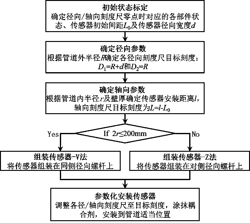
[0037] The implementation process of the parameterized installation method of the external clip-on sensor in this embodiment is as follows figure 1 As shown, the detailed steps are as follows:

[0038] Step 1: Initial State Calibration

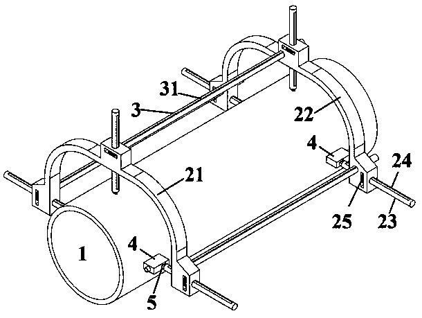
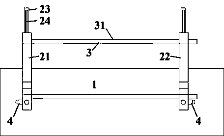
[0039] When the inner surface of the interface B end 52 is located at the axial position of the measured pipeline 1 , it is the initial state of the radial screw 23 , and at this time, the reading of the radial scale 24 is 0. When the movable frame 22 is close to the fixed frame 21, it is the initial state of the axial scale 31, at this time, the reading of the axial scale 31 is 0, assembled on the installation interface 5 The two external clip-on sensors 4, their opposite end faces are in the same plane, and the projection distance of the center point of the sensing area along the axial direction of the measured pipeline 1 is recorded as L0 .

[0040] Step 2: Determine the radial scale 24 target scale

[0041] The outer wall radius of th...

Embodiment 2

[0055] In this embodiment, a reflection method is used for measurement, and the V method is used to install the sensor. It is assumed that the inner wall radius of a certain pipeline 1 r 70mm, outer wall radius R According to the measurement technical requirements of the ultrasonic flowmeter, the installation distance of the two external clip-on sensors 4 is calculated l It is 100mm (here is a hypothetical value, which is only used for the description of the embodiment of the present invention), and the V method is used for installation, and a small-sized fixing device can be used. Measured by calibration experiments L 0 is 20mm, the projected width of the clamp-on sensor 4 in the radial direction of the measured pipeline 1 d is 30mm.

[0056] The installation parameters calculated by formulas 1~3 are: D 1 =R+d=105mm, D 2 =R=75mm, L=l-L 0 = 80mm .

[0057] One of the radial screw rods 23 on the fixed frame 21 and the movable frame 22 is respectively selected f...

Embodiment 3

[0061] In this embodiment, the direct transmission method is used for measurement, and the Z method is used to install the sensor. It is assumed that the inner wall radius of a certain pipeline 1 r 260mm, outer wall radius R is 270mm, according to the measurement technical requirements of ultrasonic flowmeter, the installation distance of two external clip-on sensors 4 is calculated l It is 240mm (here is a hypothetical value, which is only used for the description of the embodiment of the present invention), and it is installed by Z method, and a medium-sized fixing device can be used. Measured by calibration experiments L 0 is 20mm, the projected width of the clamp-on sensor 4 in the radial direction of the measured pipeline 1 d is 30mm.

[0062] The installation parameters calculated by formulas 1~3 are: D 1 =R+d=300mm, D 2 =R=270mm, L=l-L 0 = 220mm.

[0063] One of the radial screw rods 23 on the fixed frame 21 and the movable frame 22 is respectively selec...


PUM


Abstract

The invention belongs to the field of flow measurement, and provides an external clamping-type sensor parameterized installation method. An adjustable fixing device is used to install the external clamping-type sensor on the surface of a measured pipeline. The device comprises a fixed frame, a movable frame, radial screw rods, knobs and axial sliding rails, wherein the middle and the two ends of the U-shaped structure of the frame are provided with screw rod holes and sliding rail holes; the radial screw rods and the knobs are installed at the screw rod holes; and the axial sliding rails are installed at the sliding rail holes in the fixed frame and the movable frame to connect the two. The installation method comprises main steps of initial state calibration, installation parameter determination and sensor installation by the adjustable device. parameterization of the installation process and quantitative adjustment of the installation parameters are realized at the same time, the principle is concise, the operation is easy, the installation precision and the operation efficiency of the sensor can be greatly improved, and the applicability and the reusability are excellent.

Description

technical field [0001] The invention belongs to the technical field of flow measurement, and in particular relates to a parameterized installation method of an external clip-on sensor and a corresponding adjustable fixing device. Background technique [0002] Ultrasonic flowmeter (flowmeter) is a non-contact measuring instrument, based on the acoustic Doppler effect, mainly used to measure the flow (heat) of various single uniform liquids that can transmit ultrasonic waves, in chemical industry, metallurgy, medicine, water supply, etc. There are a wide range of applications in various fields. Portable / handheld ultrasonic flowmeters (energy meters) commonly used in engineering practice, the signal acquisition parts are usually clamp-on sensors. When using them, a pair of clamp-on sensors are fixed on the pipeline under test according to certain The physical parameters such as the converted flow and heat are read on the flowmeter (energy meter), and the installation distance ...

Claims


Application Information

Patent Timeline
Patent Type & Authority Applications(China)
IPC IPC(8): G01F15/18
CPCG01F15/18
Inventor 史常乐韦立新肖洋李强李明生王炎良刘全帅丁劳武刘丰
Owner 长江水利委员会水文局长江下游水文水资源勘测局
Why Eureka
Try Eureka