Circuit breaker

A circuit breaker and circuit technology, applied in the direction of protection switch operation/release mechanism, adjustment of protection switch conditions, etc., can solve the problem of circuit breaker disconnection time fluctuation, etc., and achieve the effect of short fastening reliability

Active Publication Date: 2011-08-31
MITSUBISHI ELECTRIC CORP
View PDF6 Cites 10 Cited by
  • Summary
  • Abstract
  • Description
  • Claims
  • Application Information

AI Technical Summary

Problems solved by technology

[0002] In the thermal trip device of the existing circuit breaker, the operating point of the trip mechanism, that is, the position where the bimetal plate presses the trip lever, is due to manufacturing deviations such...

Method used


Image

  • Circuit breaker
  • Circuit breaker
  • Circuit breaker

Examples


Embodiment approach 1

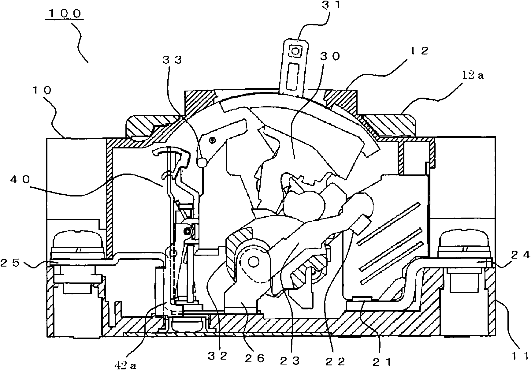
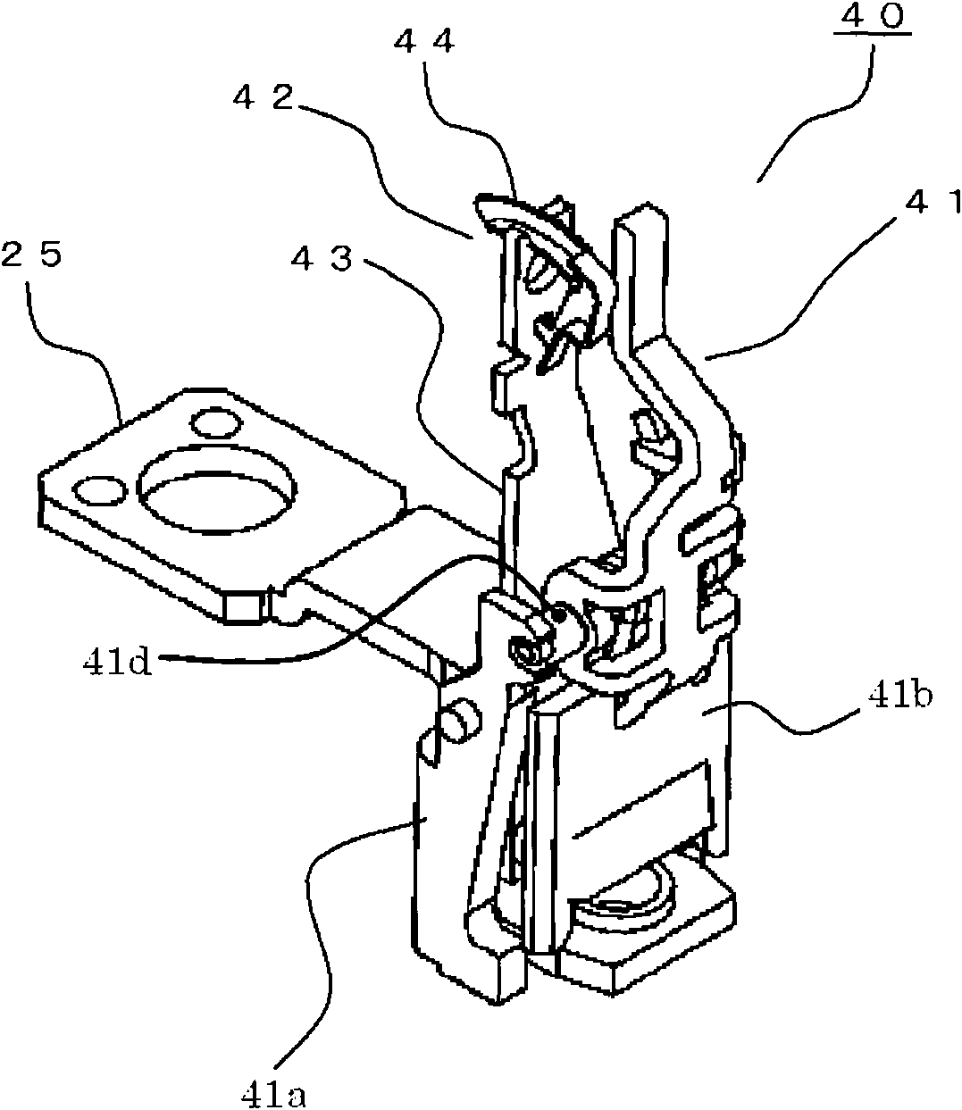
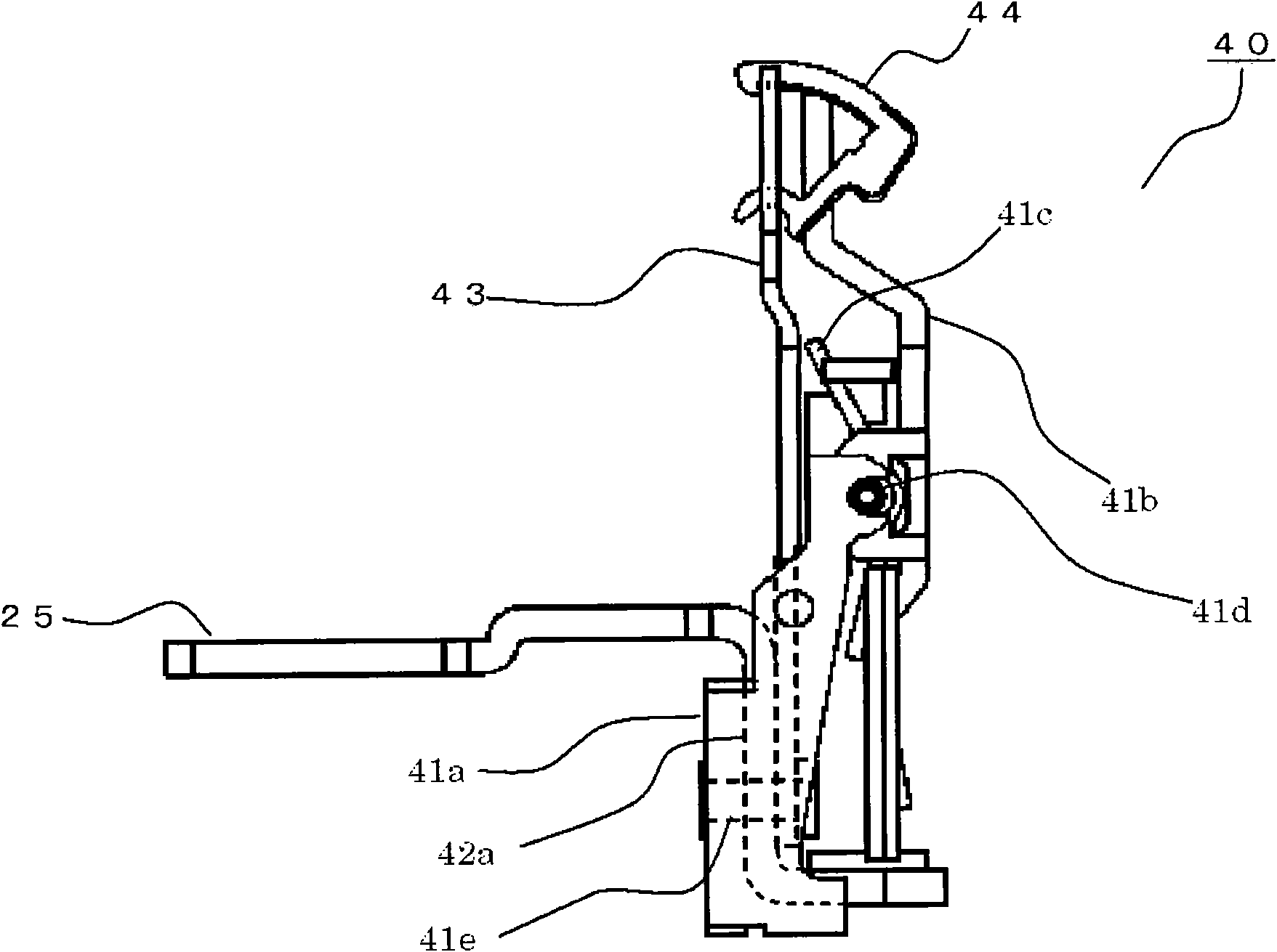
[0026] figure 1 It is a side sectional view showing the circuit breaker in Embodiment 1 of this invention, figure 2 is an oblique view showing the tripping device, image 3 is a side view showing the adjustment device, Figure 4 It is a perspective view showing the state before installing the adjustment piece to the tripping device, Figure 5 is a side view showing the adjustment of the trip device, Image 6 It is a perspective view showing the adjustment part of the tripping device.

[0027] exist figure 1 Among them, the circuit breaker 100 is constituted using a frame body 10 composed of a base 11 formed of an insulating material and a cover body 12 . On the base 11, circuit breaking units of each phase corresponding to the number of electrodes (for example, three in the case of three phases) are arranged in parallel with each other, and a known toggle lever is arranged on the upper part of the central circuit breaking unit. The switch mechanism part 30 of the mecha...

Embodiment approach 2

[0056] Figure 7 It is a side view showing the tripping device in the circuit breaker according to Embodiment 2 of the present invention, Figure 8 is a side view showing the adjustment of the trip device, Figure 9 is a perspective view showing the adjustment part of the tripping device, Figure 10 It is a plan view of the adjustment device for explaining the effect of the circuit breaker in Embodiment 2, Figure 11 It is a plan view of the trip device for explaining the problem of the circuit breaker in Embodiment 1.

[0057] In Embodiment 1, since the bottom portion 44c is not provided on the locking portion 44e of the adjuster 44, there is an advantage that processing for forming the locking portion 44e is easy. On the opposite side, in order to adjust the distance between the thermal trip device 42 and the trip bar 33 , the center of gravity of the adjustment member 44 falls on the side of the trip bar 33 , and the locking part 44e is kept locked with the guide groove ...

Embodiment approach 3

[0070] Figure 12 It is a side view showing the adjuster of the trip device in the circuit breaker according to Embodiment 3 of the present invention, Figure 13 It is a perspective view showing the adjustment part of the tripping device.

[0071] In Embodiment 1 and Embodiment 2, the abutting portion of the adjuster 44 doubles as a weight portion, but in this embodiment, as Figure 12 , 13 As shown, the weight portion 44g of the adjustment member 44 is provided separately from the contact portion 44f near the hook portion 44a. The other configurations are the same as those in Embodiment 2, so explanations are omitted.

[0072] According to this embodiment, since the weight portion 44g of the adjuster 44 is provided separately from the contact portion 44f near the hook portion 44a, the center of gravity of the adjuster 44 is closer to the hook portion 44a side. Thus, the inclination of the adjustment member 44 can be suppressed when adjusting the distance between the trip ...


PUM


Abstract

The invention provides a circuit breaker, comprising a thermal tripping device which conducts a distance adjustment between a tripping rod and an adjusting piece in quite a short time. The thermal tripping device (42) comprises a bimetallic strip (43) having a guiding groove (43a) disposed at the opening of one abutting end of the tripping rod (33), a clamping hole (43b) disposed at a regulated distance with the guiding groove (43a) in a length direction, and the adjusting piece (44). One end of the adjusting piece (44) is clamped with the clamping hole (43b) and the other end slides in the guiding groove (43a) with the clamping hole (43b) as the center, thereby the adjusting piece can rotate in a direction opposite to the deformation of the bimetallic strip (43). Under the state that the adjusting piece (44) and the tripping rod (33) abut against each other and are pushed back through the deformation of the bimetallic strip, the adjusting piece (44) is fastened on the bimetallic strip (43). The adjusting piece (44) has a bottom part (44c) sliding on the bottom face of the guiding groove (43a).

Description

technical field [0001] The invention relates to a thermal tripping device in a circuit breaker. Background technique [0002] In the thermal trip device of the existing circuit breaker, the operating point of the trip mechanism, that is, the position where the bimetal plate presses the trip lever, is due to manufacturing deviations such as processing, assembly errors, and fluctuations in material properties of the components that constitute the trip mechanism. Accumulated to produce fluctuations, causing fluctuations in the breaking time of circuit breakers. Therefore, in order to eliminate the above-mentioned manufacturing deviation, a movable adjustment member is installed on the front end of the bimetal, and an electric current is applied to the circuit breaker for a certain period of time. In a state of being in contact with the trip bar and being pushed back, the adjuster is fastened to the bimetal by laser welding (for example, refer to Patent Document 1). [0003] I...

Claims


Application Information

Patent Timeline
IPC IPC(8): H01H71/16H01H71/74
Inventor 幸本茂树丹羽伸次郎冈本直树
Owner MITSUBISHI ELECTRIC CORP
Why Eureka
Try Eureka