Circuit breaker
A circuit breaker and circuit technology, applied in the direction of protection switch operation/release mechanism, adjustment of protection switch conditions, etc., can solve the problem of circuit breaker disconnection time fluctuation, etc., and achieve the effect of short fastening reliability
- Summary
- Abstract
- Description
- Claims
- Application Information
AI Technical Summary
Problems solved by technology
Method used
Image
Examples
Embodiment approach 1
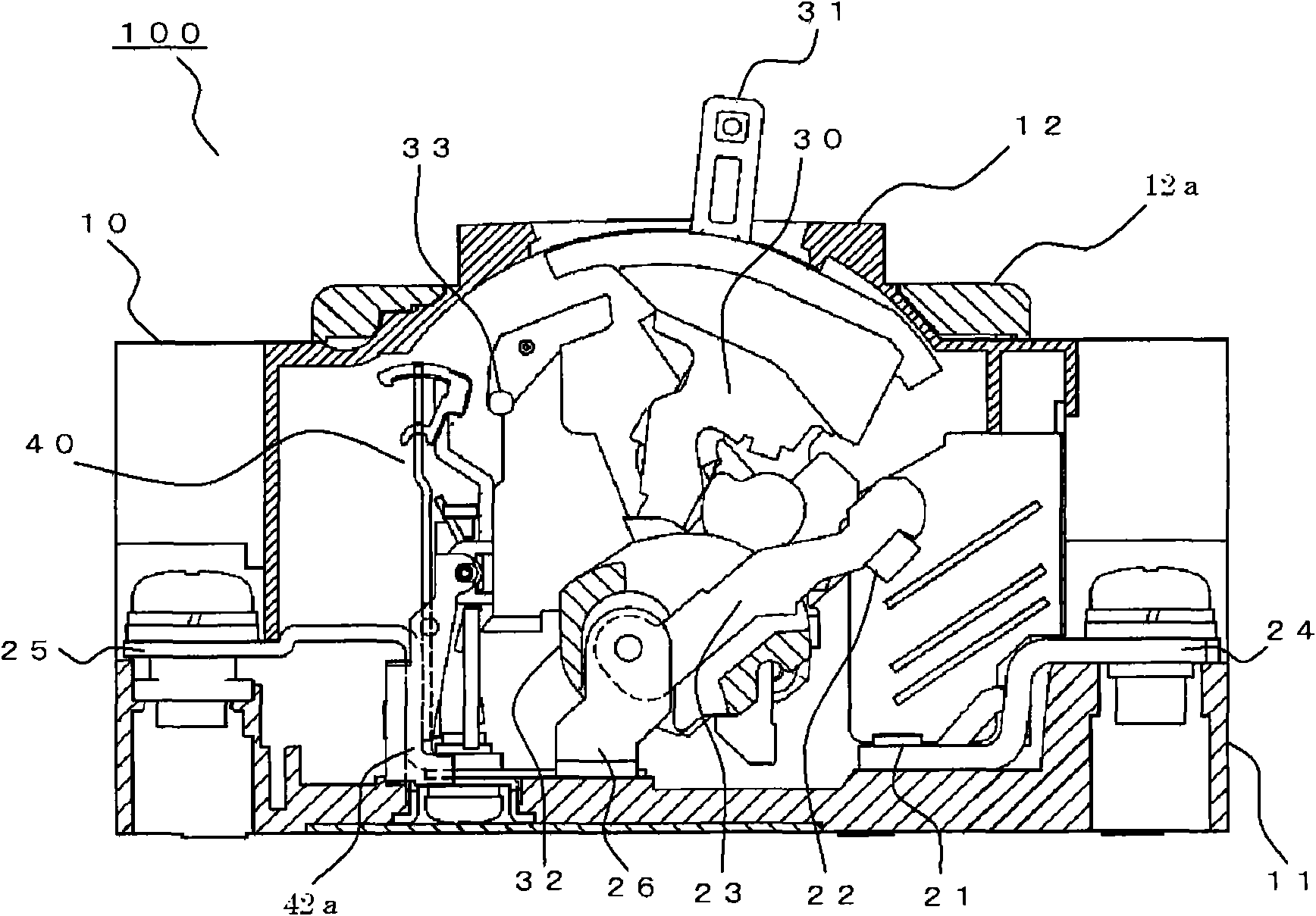
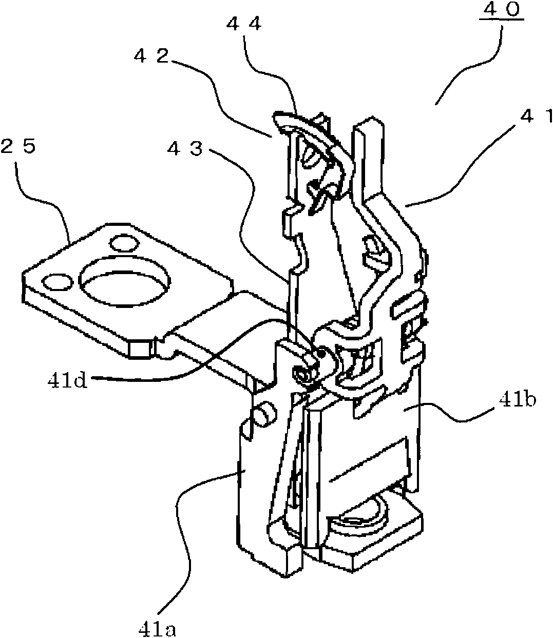
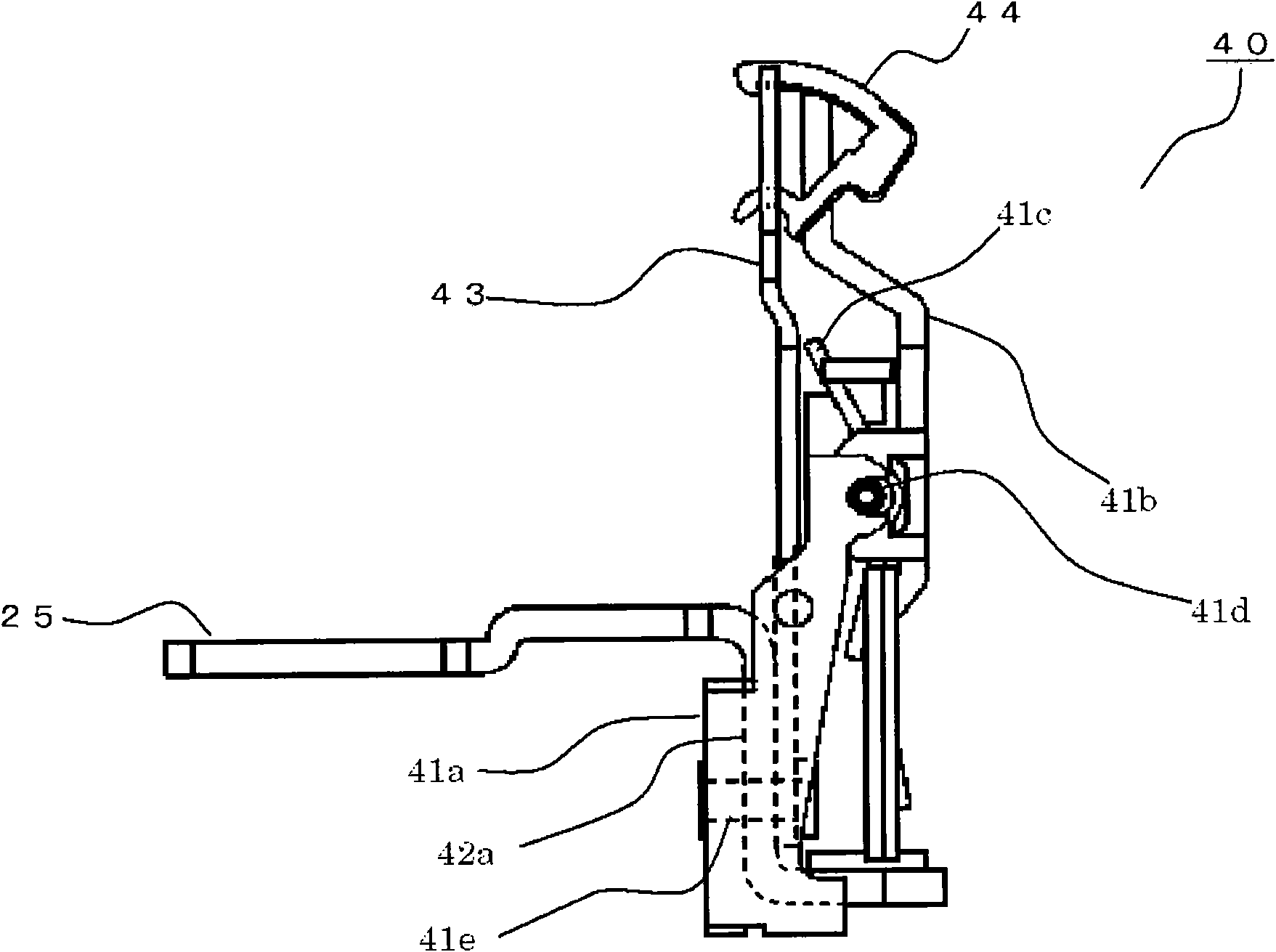
[0026] figure 1 It is a side sectional view showing the circuit breaker in Embodiment 1 of this invention, figure 2 is an oblique view showing the tripping device, image 3 is a side view showing the adjustment device, Figure 4 It is a perspective view showing the state before installing the adjustment piece to the tripping device, Figure 5 is a side view showing the adjustment of the trip device, Figure 6 It is a perspective view showing the adjustment part of the tripping device.
[0027] exist figure 1 Among them, the circuit breaker 100 is constituted using a frame body 10 composed of a base 11 formed of an insulating material and a cover body 12 . On the base 11, circuit breaking units of each phase corresponding to the number of electrodes (for example, three in the case of three phases) are arranged in parallel with each other, and a known toggle lever is arranged on the upper part of the central circuit breaking unit. The switch mechanism part 30 of the mech...
Embodiment approach 2
[0056] Figure 7 It is a side view showing the tripping device in the circuit breaker according to Embodiment 2 of the present invention, Figure 8 is a side view showing the adjustment of the trip device, Figure 9 is a perspective view showing the adjustment part of the tripping device, Figure 10 It is a plan view of the adjustment device for explaining the effect of the circuit breaker in Embodiment 2, Figure 11 It is a plan view of the trip device for explaining the problem of the circuit breaker in Embodiment 1.
[0057] In Embodiment 1, since the bottom portion 44c is not provided on the locking portion 44e of the adjuster 44, there is an advantage that processing for forming the locking portion 44e is easy. On the opposite side, in order to adjust the distance between the thermal trip device 42 and the trip bar 33 , the center of gravity of the adjustment member 44 falls on the side of the trip bar 33 , and the locking part 44e is kept locked with the guide groove ...
Embodiment approach 3
[0070] Figure 12 It is a side view showing the adjuster of the trip device in the circuit breaker according to Embodiment 3 of the present invention, Figure 13 It is a perspective view showing the adjustment part of the tripping device.
[0071] In Embodiment 1 and Embodiment 2, the abutting portion of the adjuster 44 doubles as a weight portion, but in this embodiment, as Figure 12 , 13 As shown, the weight portion 44g of the adjustment member 44 is provided separately from the contact portion 44f near the hook portion 44a. The other configurations are the same as those in Embodiment 2, so explanations are omitted.
[0072] According to the present embodiment, since the weight portion 44g of the adjuster 44 is provided separately from the contact portion 44f near the hook portion 44a, the center of gravity of the adjuster 44 is closer to the hook portion 44a side. Thus, the inclination of the adjustment member 44 can be suppressed when adjusting the distance between th...
PUM
 Abstract
Description
Claims
Application Information
 - R&D
- Intellectual Property
- Life Sciences
- Materials
- Tech Scout
- Unparalleled Data Quality
- Higher Quality Content
- 60% Fewer Hallucinations
Browse by: Latest US Patents, China's latest patents, Technical Efficacy Thesaurus, Application Domain, Technology Topic, Popular Technical Reports.
© 2025 PatSnap. All rights reserved.Legal|Privacy policy|Modern Slavery Act Transparency Statement|Sitemap|About US| Contact US: help@patsnap.com


