
Forging process for nuclear power rotor and other large shaft parts

A technology of shaft parts and rotors, which is applied in the field of shaft parts, can solve the problems of hydraulic press space limitation, large forging size, and no heating effect, etc., and achieve the effect of solving equipment overload, uniform margin, and strengthening heating effect

Active Publication Date: 2011-09-07
CHINA ERZHONG GRP DEYANG HEAVY IND
View PDF7 Cites 17 Cited by
  • Summary
  • Abstract
  • Description
  • Claims
  • Application Information

AI Technical Summary

Problems solved by technology

The disadvantage of this method is that it is limited by the space of the hydraulic press, and the number of pulling trips is less, and the second is that the heating effect before upsetting does not increase.
[0010] 3) Due to the large size of the forging, the operation is difficult, and the workload of each fire is limited, so the deformation is difficult to synchronize
[0013] like Image 6 As shown, the existing "central compaction method" is to place the flat square 7 on the lower wide anvil 9 and forge it through the upper narrow anvil 8, and only one side of the flat square 7 can be operated at a time

Method used


Image

  • Forging process for nuclear power rotor and other large shaft parts
  • Forging process for nuclear power rotor and other large shaft parts
  • Forging process for nuclear power rotor and other large shaft parts

Examples


Embodiment Construction

[0035] Taking the production of 1100MW nuclear power rotor as an example, the forging process of the present invention will be described in detail in conjunction with the accompanying drawings.

[0036] step 1)

[0037] Firstly, the steel ingot ingot with a weight of 550t is wrapped around the steel ingot body with a single traveling plate chain, so as to press out the jaws from the riser of the steel ingot;

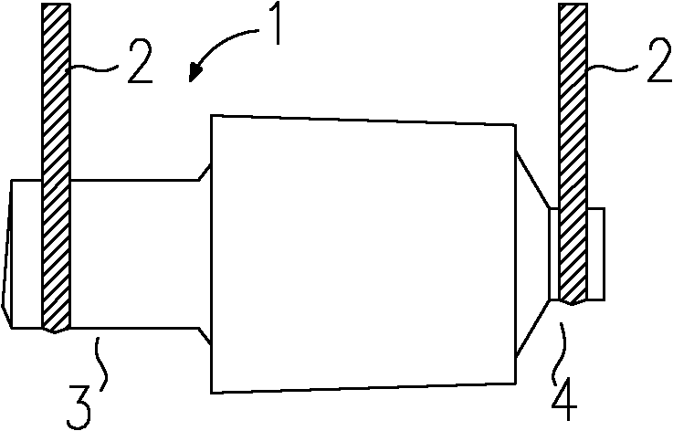
[0038] Then, if figure 1 As shown in the figure, two traveling cranes respectively pass the respective plate chains 2 to enclose the ingot tail 4 and the jaw 3 pressed out from the riser, and use the WHF method to pull out the steel ingot 1 into a flat square 5;

[0039] Finally, a new jaw is extruded at the ingot body near the ingot tail 4, and the old jaw 3 is cut off.

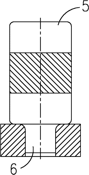
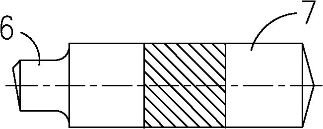
[0040] Such as Figure 2 ~ Figure 4 As shown, when implementing steps 2) to 4), new jaws 6 are used.

[0041] Step 2)

[0042] Such as figure 2 As shown, the vertical upsetting is carried out t...


PUM


Abstract

The invention discloses a forging process for nuclear power rotor and other large shaft parts, which can be used for effectively solving the forging problem of a high-grade rotor with a super large specification. The process specifically comprises the following steps of: (1) drawing out a steel ingot to form a flat square by using a WHF (Wide die Heavy blow Forging) method; (2) performing erecting and upsetting on the flat square; (3) drawing out the upset steel billet to the flat square again by using the WHF method; and (4) compacting the four sides and the center of the flat square, wherein the 'flat square' specifically means a cuboid-shaped steel billet. In accordance with the result of flaw detection (UT(Ultrasonic Test) and MT (Magnetic particle Test)), no flaw (phi is above 0.6), for which recording is required, is found in a 1100MW rotor piece manufactured by using 550t steel billets, and the quality is superior; based on the dimension of a workpiece, all the dimensions of various parts of a forge piece can meet the processing requirement, and the forging allowance is uniform; the control state of forging grain size is deduced from a UT state subsequent to thermal treatment after forging, the desired effect is completely achieved, and no phenomenon of coarse crystal or mixed crystal happens.

Description

technical field [0001] The invention relates to a shaft part, especially a forging process of super-large and high-grade nuclear power rotors. Background technique [0002] In the past, the forging process for conventional nuclear power rotors was as follows: [0003] 1) Cut off the ingot tail of the steel ingot, and press the jaws on the riser end of the steel ingot; [0004] 2) After the sleeve is put on the jaw, a single driving operation is used to perform one or more upsetting of the steel billet; [0005] 3) Rolling and drawing to lengthen the material; [0006] 4) Trim and produce the finished rotor. [0007] However, when the applicant of the present application used the above-mentioned process to produce the first 1100MW nuclear power rotor in China (the total length of the part is 15226mm, the maximum cross-sectional diameter size φ1955mm), it was found that the above-mentioned conventional rotor forging technology is not suitable for the production of super-lar...

Claims


Application Information

Patent Timeline
Patent Type & Authority Applications(China)
IPC IPC(8): B21K1/06
Inventor 孙嫘孙海燕沈国劬张清华
Owner CHINA ERZHONG GRP DEYANG HEAVY IND
Learn More