Slide linkage structure for drawers
A sliding rail connection and drawer technology, which is applied in the direction of drawers, furniture parts, household appliances, etc., to achieve the effects of reliable connection, simple and reasonable structure, and long service life
- Summary
- Abstract
- Description
- Claims
- Application Information
AI Technical Summary
Problems solved by technology
Method used
Image
Examples
no. 1 example
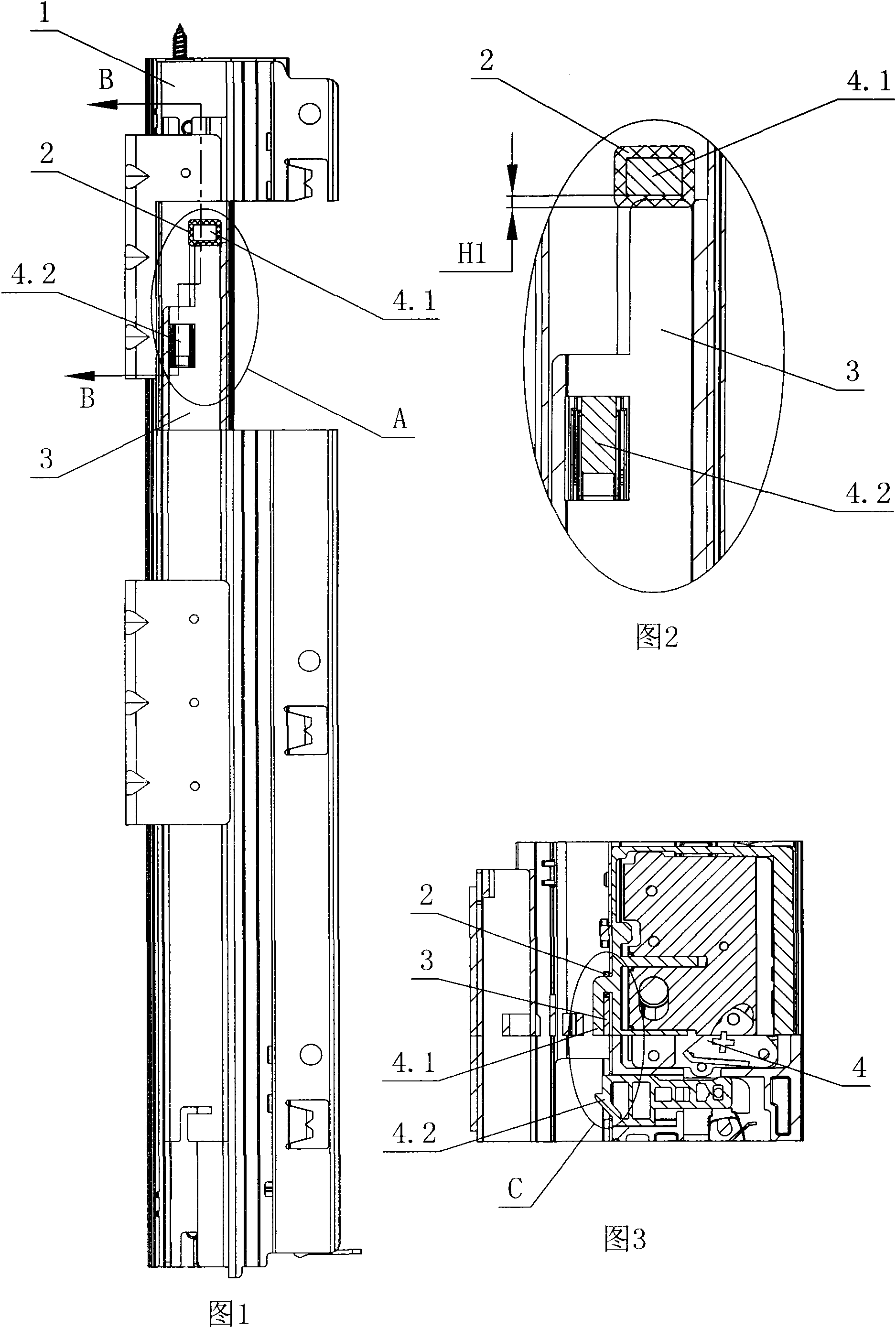
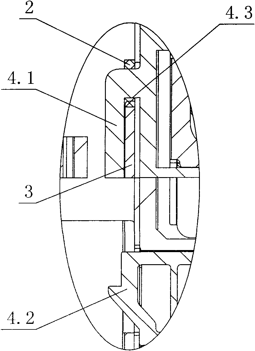
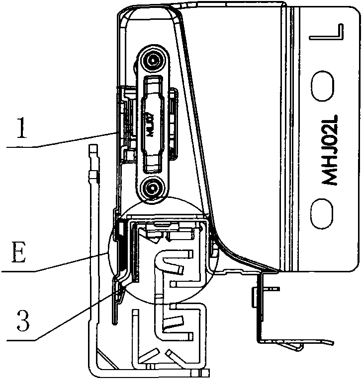
[0028] see Figure 1-Figure 8 , the drawer slide rail connection structure includes a drawer side panel 1 with a panel adjustment device 4 inside, and the front and rear sides of the bottom of the panel adjustment device are respectively provided with a catch hook 4.1 that prevents the moving rail 3 of the slide rail from advancing and a lock that prevents the moving rail from retreating. Tongue 4.2, the catch hook and the lock tongue protrude from the bottom of the side plate of the drawer and connect with the moving rail; the front end of the top of the moving rail is inserted into the catch hook, the front end face 3.1 of the moving rail is in contact with the inner end face 4.3 of the catch hook, and the rear of the front face of the moving rail corresponds The dead bolt is provided with a stop hole 3.2. A gap eliminating component is arranged between the front end surface 3.1 of the moving rail and the inner end surface 4.3 of the retaining hook.
[0029] The gap elimina...
no. 2 example
[0032] see Figure 9-Figure 12 , The gap eliminating component is a cushion 2' made of soft material, which is fixedly connected with the inner end surface 4.3 of the retaining hook in advance by an adhesive. The distance between the front end surface of the lock tongue 4.2 and the inner end surface 4.3 of the retaining hook is L1, the distance between the front end surface of the stop hole 3.2 and the front end surface 4.1 of the moving rail is L2, and the thickness of the cushion 2' is H2; among them, L1 - H2≤L2<L1.
[0033] The above cushion 2' can also be fixedly connected to the front end surface 4.1 of the moving rail in advance through an adhesive, then L2L2. Other unmentioned parts are the same as the first embodiment.
PUM
 Abstract
Description
Claims
Application Information
 - R&D
- Intellectual Property
- Life Sciences
- Materials
- Tech Scout
- Unparalleled Data Quality
- Higher Quality Content
- 60% Fewer Hallucinations
Browse by: Latest US Patents, China's latest patents, Technical Efficacy Thesaurus, Application Domain, Technology Topic, Popular Technical Reports.
© 2025 PatSnap. All rights reserved.Legal|Privacy policy|Modern Slavery Act Transparency Statement|Sitemap|About US| Contact US: help@patsnap.com


