Self-postponed wind driven generator
A wind-driven generator, self-slowing technology, applied in the direction of wind-driven engine, wind-driven motor combination, wind power generation, etc., can solve the problems of poor economic benefits of wind-driven generators, insufficient power generation, complicated installation, etc., to improve protection and use Effects of life, reduction of material composition, and improvement of power generation
- Summary
- Abstract
- Description
- Claims
- Application Information
AI Technical Summary
Problems solved by technology
Method used
Image
Examples
Embodiment 1
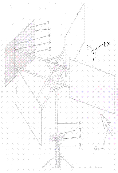
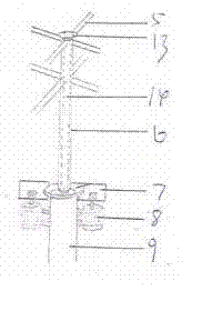
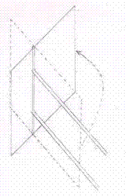
[0020] The self-slowing wind power generator of the present invention comprises a steel frame 9 installed on the ground, a vertically upward pole fixed on the steel frame and a wind wing 1 installed on the top of the pole through a strut 5; the strut 5 is A horizontal cross or triangle, each end of which is vertically equipped with a wind wing 1, and a vertical middle beam 3 is arranged at the transverse third of each wind wing (the position of this middle beam is no more than Two-fifths, but more than one-third of the resistance will be more and more) fixed on the edge of the frame, so that one-third of the wind wing is outside the strut, and the center beam is rotatably installed at the end of the strut A casing 6 is sleeved outside the rod column through a bearing, the strut is fixed on the upper end of the casing, and at least one generator 8 is installed at the corresponding position between the steel frame 9 and the casing 6 . Rectangular wind wing 1 is installed in meta...
Embodiment 2
[0037] The self-slowing wind power generator of the present invention comprises a steel frame 9 installed on the ground, a vertically upward pole column fixed on the steel frame and a wind wing 1 installed on the top of the pole column through a strut 5; the strut 5 is A cross bar, the middle part of which is rotatably installed on the top of the pole column, and a plurality of wind wing brackets 18 with the cross bar as the rotating shaft are respectively installed at both ends, and the wind wing 1 is hinged on the horizontal bar of the wind wing support, and the generator 8 is installed in the contact place of strut 5 and pole post top. The rectangular wings are made of canvas mounted within a metal frame. A horizontal middle beam 3 is fixed on the frame limit at the vertical third place of each wind wing, and the middle beam is rotatably installed on the horizontal bar of the wind wing support 18 .
PUM
 Abstract
Description
Claims
Application Information
 - R&D
- Intellectual Property
- Life Sciences
- Materials
- Tech Scout
- Unparalleled Data Quality
- Higher Quality Content
- 60% Fewer Hallucinations
Browse by: Latest US Patents, China's latest patents, Technical Efficacy Thesaurus, Application Domain, Technology Topic, Popular Technical Reports.
© 2025 PatSnap. All rights reserved.Legal|Privacy policy|Modern Slavery Act Transparency Statement|Sitemap|About US| Contact US: help@patsnap.com


