
Hydraulic control system, hydraulic control module thereof and engineering machinery with hydraulic control system

A control module and hydraulic technology, applied in the hydraulic field, can solve the problems of pressure oil delay, complex oil flow path process, large oil pump load, etc., and achieve the effect of reducing load

Active Publication Date: 2012-11-14
ZOOMLION HEAVY IND CO LTD
View PDF0 Cites 0 Cited by
  • Summary
  • Abstract
  • Description
  • Claims
  • Application Information

AI Technical Summary

Problems solved by technology

Therefore, the oil flow path process is complex and easily affected
The connection between the components in the hydraulic control module is realized by the oil channel processed inside the bottom plate. The oil channel is complex and difficult to process, and the residual impurities are not easy to remove
The long oil channel is easy to delay the pressure oil controlling the hydraulic multi-way valve, causing the crane to lag behind
[0006] In addition, it can be seen from the above that the hydraulic control module in the hydraulic control system needs the oil pump connected to its oil inlet to be in the oil supply state all the time, and the oil pump is subjected to a large load

Method used


Image

  • Hydraulic control system, hydraulic control module thereof and engineering machinery with hydraulic control system

Examples


Embodiment Construction

[0027] The embodiments of the present invention will be described in detail below with reference to the accompanying drawings, but the present invention can be implemented in many different ways defined and covered by the claims.

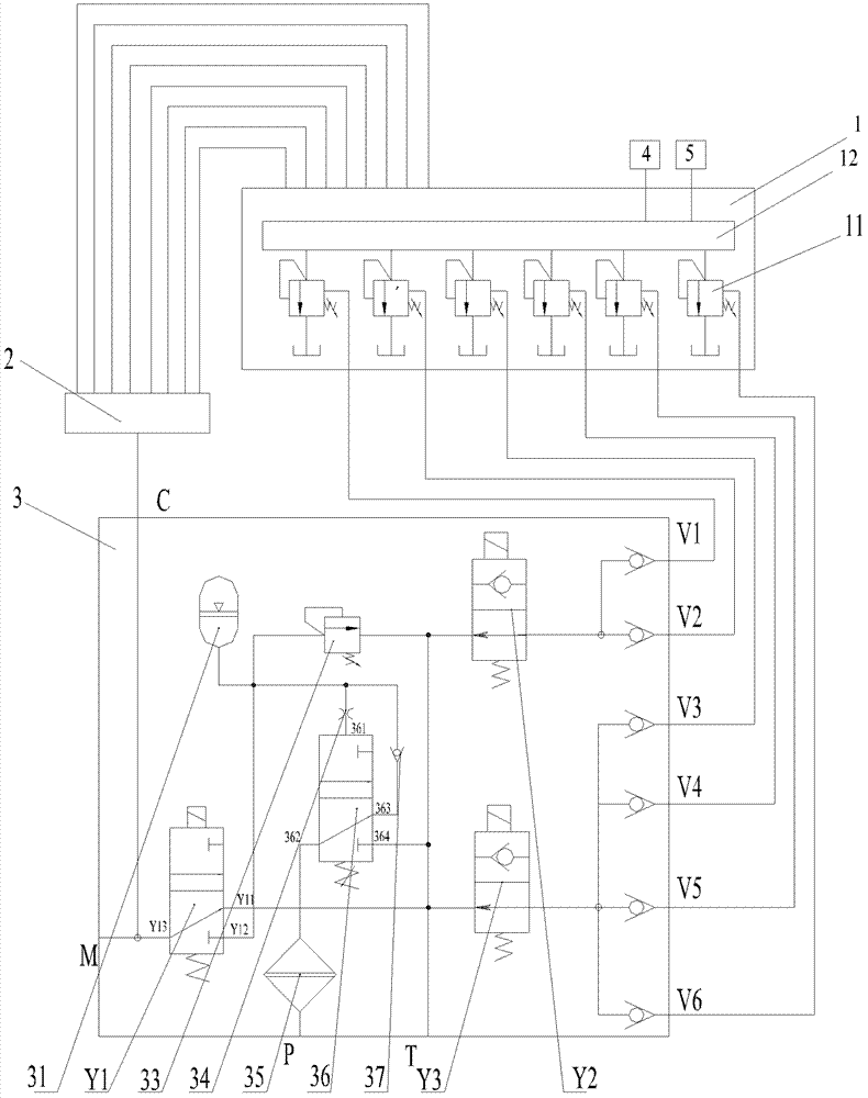
[0028] Such as figure 1 As shown, the hydraulic control module 3 according to the embodiment of the present invention includes an oil inlet P, a working oil port C, an oil return port T, valves Y2, Y3 and an unloading port. The oil inlet P is connected to an oil pump (not shown in the figure). The working oil port C is connected to hydraulic components outside the hydraulic control module 3 to supply hydraulic oil thereto. The oil inlet of each valve Y2, Y3 is connected to one or more unloading ports. In this embodiment, the valve Y2 is connected to the two oil unloading ports on the upper right, and the valve Y3 is connected to the four unloading ports on the lower right. oil port. The oil outlet of each two-position two-way solenoid valve Y2, Y...


PUM


Abstract

The invention discloses a hydraulic control system, a hydraulic control module thereof and engineering machinery with the hydraulic control system. The hydraulic control module comprises an oil inlet (P), a working oil port (C), an oil return port (T), one or more unloading ports and one or more valves (Y2, Y3), wherein the oil inlet (P) is connected to an oil pump; the oil inlet of each valve (Y2, Y3) is connected to one or more unloading ports; and the oil outlet of each valve (Y2, Y3) is connected to the oil return port (T). The hydraulic control module plays a role in unloading hydraulic elements in case of emergency, thus the hydraulic system is ensured to be not out of order.

Description

technical field [0001] The invention relates to the hydraulic field, in particular to a hydraulic control system, a hydraulic control module thereof, and an engineering machine with the hydraulic control system. Background technique [0002] There is an existing hydraulic control system in construction machinery, which includes multiple hydraulic reversing valves, multiple pilot pressure reducing valves, and a hydraulic control module. Each hydraulic reversing valve is set in a main oil circuit in the hydraulic control system to control the on-off of the main oil circuit, and then indirectly control the actuators such as oil cylinders or hydraulic motors connected to the main oil circuit. The pilot pressure reducing valve is used to control the action of the hydraulic reversing valve. Wherein, the hydraulic control module is connected with the pilot pressure reducing valve and the hydraulic reversing valve at the same time, controls the action of the pilot reducing valve, a...

Claims


Application Information

Patent Timeline
Patent Type & Authority Patents(China)
IPC IPC(8): F15B11/00
CPCF15B20/00F15B11/00
Inventor 李永星宋建清
Owner ZOOMLION HEAVY IND CO LTD
Learn More