Arc extinguishing equipment of moulded case circuit breaker

A technology of molded case circuit breaker and arc extinguishing device, which is applied in the direction of circuit breaker components, etc., can solve the problems of air blowing pressure drop in the arc extinguishing chamber, grid short-circuiting, insufficient air blowing pressure strength, etc., and achieve enhanced current limiting performance , Improve the effect of breaking and easy installation

Inactive Publication Date: 2011-09-14
JIANGSU PHONO ELECTRIC
View PDF2 Cites 12 Cited by
  • Summary
  • Abstract
  • Description
  • Claims
  • Application Information

AI Technical Summary

Problems solved by technology

However, since there is an opening at the rear of the arc extinguishing chamber for the moving contact to enter the arc extinguishing chamber, during the process of gas blowing and extinguishing the arc in the arc extinguishing chamber, a part of the gas moves towards the rear opening, causing the entire arc extinguishing The drop of air blowing pressure in the chamber weakens the effect of air blowing, which is not conducive to improving the arc extinguishing performance of the circuit breaker
Moreover, when the circuit breaker is disconnected, due to insufficient air blowing pressure, the metal particles produced by the arc or arc burnt contacts will adhere to the grids, causing a short circuit between the grids and reducing the breaking performance of the circuit breaker.

Method used


Image

  • Arc extinguishing equipment of moulded case circuit breaker
  • Arc extinguishing equipment of moulded case circuit breaker
  • Arc extinguishing equipment of moulded case circuit breaker

Examples


Embodiment Construction

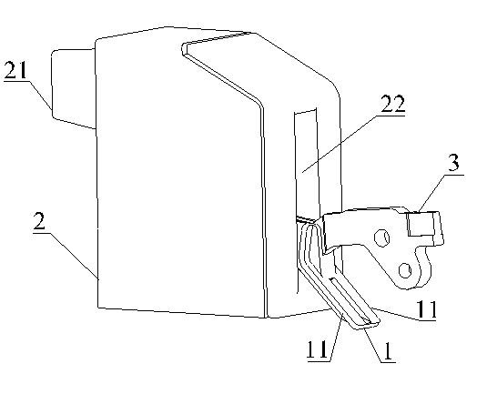
[0017] see image 3 and Figure 4 , the present invention has an arc extinguishing chamber 2, the arc extinguishing chamber 2 is a cavity structure, an air outlet 21 is arranged on the front wall of the arc extinguishing chamber 2, and a rear opening 22 is opened on the rear wall of the arc extinguishing chamber 2, so as to Make way for the action of moving contact 3. The front end of the moving contact 3 extends into the inner cavity of the arc extinguishing chamber 2 from the outside through the rear opening 22 , and the moving contact 3 moves up and down along the rear opening 22 during the opening and closing process of the circuit breaker.

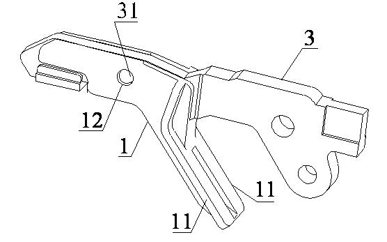
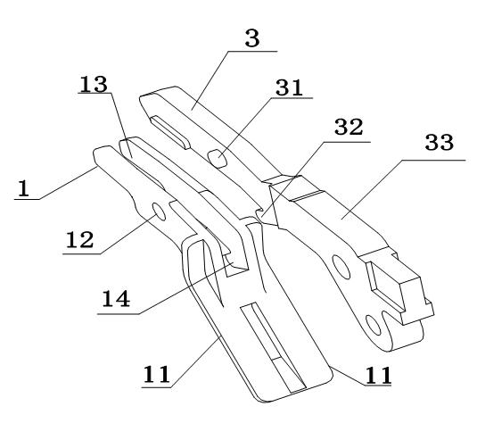
[0018] see figure 1 and 2 As shown, the present invention connects a movable contact plastic part 1 at the front end of the movable contact 3, and the movable contact plastic part 1 is divided into front and rear parts, and the front part is used for fixedly connecting the movable contact 3. The front part has a groove 13, and rou...


PUM


Abstract

The invention discloses an arc extinguishing equipment of a moulded case circuit breaker. The front wall of an arc extinguish chamber is provided with a gas outlet, and the rear wall is provided with a rear opening; the front end of a moving contact stretches into the cavity of the arc extinguish chamber from the exterior through the rear opening; the front end of the moving contact is connected with a moving contact plastic part; the front part of the moving contact plastic part is provided with a groove wrapping the front end of the moving contact; two side walls of the groove are provided with round holes; the moving contact is provided with circular platforms matched with the round holes; the rear end of the groove is provided with a channel; the moving contact is provided with a bard-shaped boss clamped into the channel; the front part of the moving contact plastic part extends towards the rear inferior and is bent with a rear boss; in the repelling process of the moving contact, the rear boss moves to the position which can block the rear opening along with the moving contact to block the rear opening of the arc extinguish chamber to the greatest extent so as to enhance the pressure in the arc extinguish chamber and enhance the air-blowing function in the arc extinguish chamber, and the arc extinguishing equipment can effectively improve the disjunction of the moulded case circuit breaker and enhance the current-limiting performance.

Description

technical field [0001] The invention relates to a molded case circuit breaker, in particular to an arc extinguishing device of the molded case circuit breaker, and belongs to the technical field of low-voltage electrics. Background technique [0002] The arc extinguishing chambers of existing molded case circuit breakers are generally composed of arc extinguishing grids and gas-generating materials. When the circuit breaker is disconnected, the moving and static contacts are repelled and an arc is generated. Since the contact movement route of the moving contact is in the cavity of the arc extinguishing grid of the arc extinguishing device, the arc enters the arc extinguishing grid under the action of electromotive force, and cuts the arc into a series of short arcs in series, making the arc thinner And quickly increase the arc voltage, so as to achieve the role of arc extinguishing. At the same time, the gas-generating material will generate gas when the circuit breaker i...

Claims


Application Information

Patent Timeline
Patent Type & Authority Applications(China)
IPC IPC(8): H01H73/18
Inventor 任飞陈德桂严丽君
Owner JIANGSU PHONO ELECTRIC
Why Eureka
Try Eureka