Machining unit

A technology for processing machines and workpieces, which is applied in the direction of metal processing machine parts, metal processing equipment, manufacturing tools, etc., can solve the problems of high holding force, impossibility, cost, etc., to improve the clamping process, expand the scope of use, and improve clamping The effect of tightening

Active Publication Date: 2011-09-21
GROB WERKE & K G
View PDF9 Cites 9 Cited by
  • Summary
  • Abstract
  • Description
  • Claims
  • Application Information

AI Technical Summary

Problems solved by technology

Often, however, the workpiece table can also be rotated in space, and a reliable hydraulic supply must also be ensured in the rotated position, which can only be achieved with considerable effort not only in the design but also in the maintenance of the rotatable elements.
[0009] Alternatively, it is known to use pneumatic workholding devices, but in which such high holding forces cannot be achieved
[0010] Here too, the problem arises that position interrogation, such as workpiece clamped or machining tool clamped, can only be interrogated indirectly via pressure or via other, often expensive, devices
[0011] Finally, the technical outlay for the installation of the hydraulic system is also considerable, since in addition to the arrangement of the piping and the arrangement of the connecting hoses or flexible pipes, corresponding pump assemblies as well as valves and valve controls are also required

Method used


Image

  • Machining unit
  • Machining unit
  • Machining unit

Examples


Embodiment Construction

[0070] Elements that are identical or correspond to one another in the figures are denoted with the same reference numerals and are therefore not described again unless this is intended.

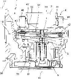
[0071] exist figure 1 The invention is schematically shown in . The processing machine 1 includes on the one hand a workpiece table 3 which holds a workpiece 2 . exist figure 1 A machining tool not shown in the figure is driven by the tool spindle and can be moved in a suitable manner relative to the workpiece 2 , and is formed, for example, as a drill or a milling cutter. The processing machine 1 according to the invention has a plurality of axes. Provision is made for machining to be as flexible as possible, that the workpiece 2 can be positioned relative to the machining tool along three spatial axes. In addition to these longitudinal axes, however, rotational axes are also provided. The first axis of rotation is shown with reference numeral 10 and is called the B-axis. It allows th...


PUM


Abstract

The invention refers to a machine tool for machining one or more work pieces, wherein the work piece is held indirectly or directly by a clamping device in the machine tool on or at a non-rotary work piece table or a work piece table rotating around at least one axis. The invention is characterized in that the clamping device comprises at least one clamping element interacting indirectly or directly with the work piece, and an electric motor is provided for generating the clamping power that is in active connection with the clamping element.

Description

technical field [0001] The invention relates to a processing machine for processing one or more workpieces, in which the workpieces are fixed indirectly or directly by means of clamping devices on or in a non-rotatable workpiece table, or in particular fixed about at least one axis On or in a rotatable workpiece table. [0002] In addition, the invention also includes a processing machine for processing one or more workpieces with a non-rotatable processing tool or a processing tool driven in rotation by a tool spindle, which is fixed indirectly or directly in a tool receptacle via a tool clamping device. Ministry. Background technique [0003] The homogeneous processing machine is, for example, part of a complex processing line, in particular a machining line, or is also realized in a preferably flexibly usable processing center. The cutting tools of similar processing machines generally have high rotational speed. The other forces that occur during machining are absolut...

Claims


Application Information

Patent Timeline
Patent Type & Authority Applications(China)
IPC IPC(8): B23Q1/52B23Q5/10B23Q3/00B23Q1/25
CPCB23Q1/0009B23Q3/06B23Q1/76B23Q5/04B23Q5/22B23Q2703/02B23Q2703/12B24B1/04
Inventor B·格鲁博
Owner GROB WERKE & K G
Why Eureka
Try Eureka