Movable concrete mixing plant

A technology for mixing equipment and concrete, applied in mixing plants, clay preparation equipment, cement mixing equipment, etc., can solve the problems of complex structure and inability to use flexibly enough, and achieve the effect of simple structure

Inactive Publication Date: 2011-09-21
LIEBHERR MISCHTECHN
View PDF10 Cites 8 Cited by
  • Summary
  • Abstract
  • Description
  • Claims
  • Application Information

AI Technical Summary

Problems solved by technology

However, known mobile concrete mixing plants are too complex in construction and cannot be used flexibly enough

Method used


Image

  • Movable concrete mixing plant
  • Movable concrete mixing plant
  • Movable concrete mixing plant

Examples


Embodiment Construction

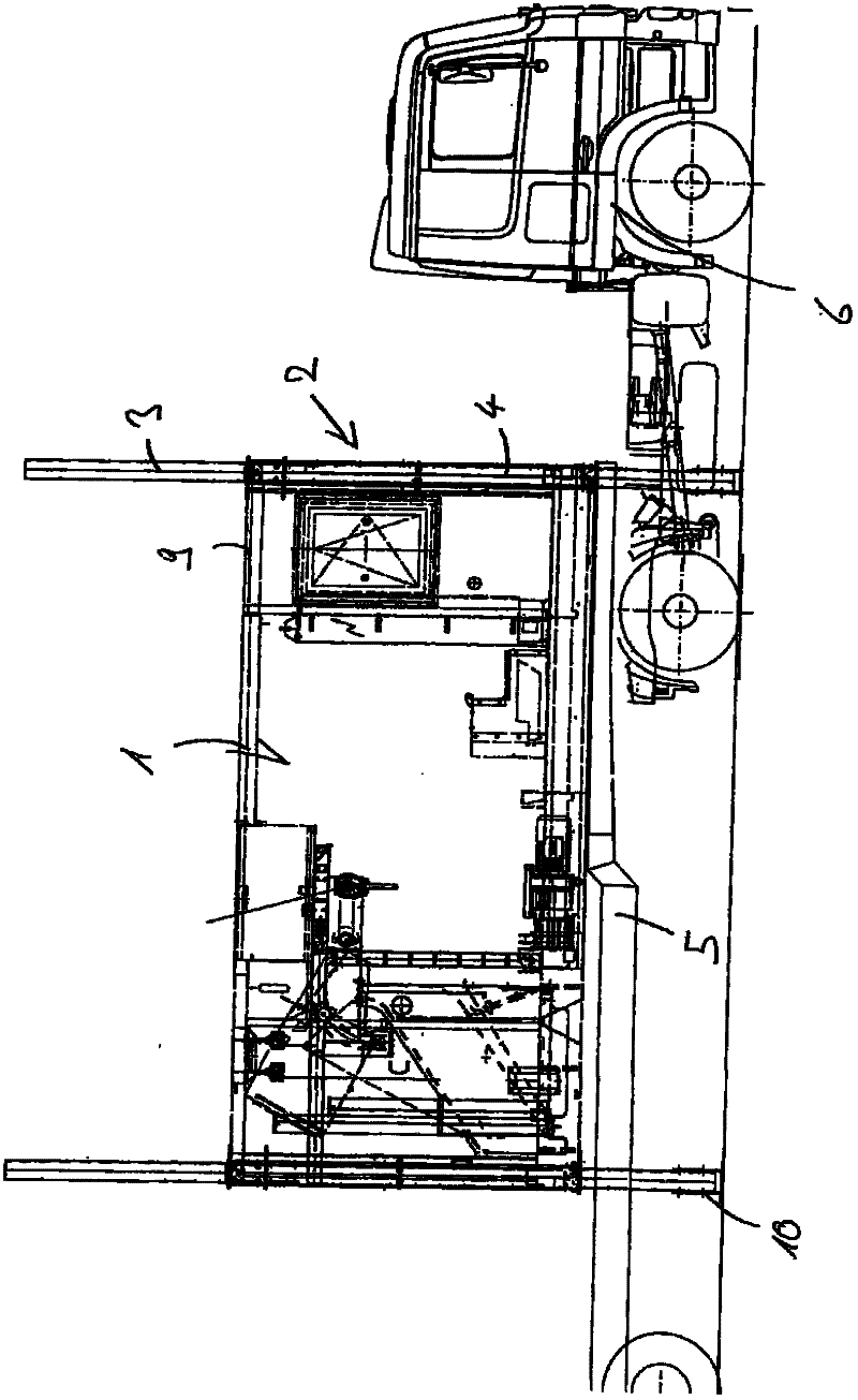
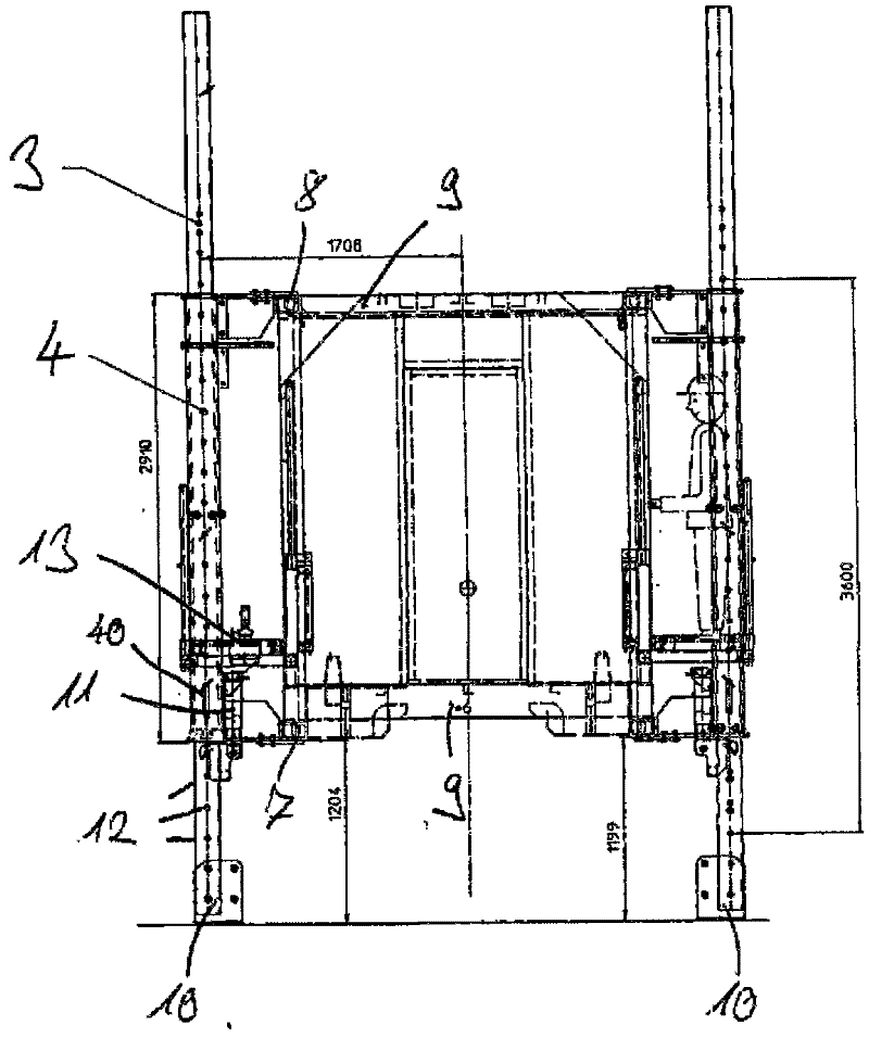
[0051] now by means of Figures 1 to 4 A first embodiment of the mixing unit of the mobile concrete mixing plant according to the present invention is shown in detail. Here, the mixing unit 1 has the shape of a container. For this purpose, the stirring unit has a cuboid-shaped frame 9 consisting of corresponding metal supports, which frame forms the supporting structure of the stirring unit 1 . The mixing unit 1 can thus be transported without problems on the loading surface 5 of the transport trolley 6 . In this case, it is provided in the exemplary embodiment that the mixing unit has the dimensions of a typical 20-inch container. Here, the stirring unit is a pre-installed functional unit.

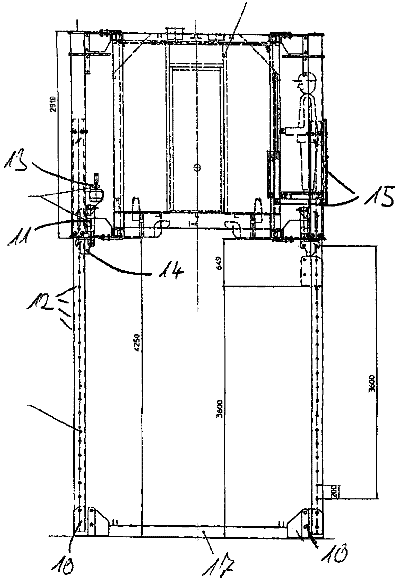
[0052] In order to operate a mobile concrete mixing plant, the mixing unit must be lifted into a working position in which a concrete mixer truck can drive under the mixing unit and fill it with concrete from above. In particular, a working height of 4.25 meters is required for this p...


PUM


Abstract

The invention relates to a movable concrete mixing plant, which comprises at least one structural unit, specifically a stirring unit and a lifting device, wherein the structural unit is lifted in a work position by the lifting device and supported relatively to the ground; a concrete mixer is loaded through the structural unit in a work position; and the structural unit can be transported on the loading surface of a transport vehicle, specifically the loading surface of a semi-trailer towing vehicle.

Description

technical field [0001] The invention relates to a concrete mixing plant having at least one structural unit, in particular a mixing unit, and a lifting device, wherein the structural unit is lifted into a working position by the lifting device and can be supported relative to the ground. In this working position of the structural unit, the concrete mixer truck can be loaded with concrete from the structural unit. It is advantageous here that the concrete mixer truck can be driven under the structural unit and filled from above. Background technique [0002] It is already known to integrate the stirring unit and the lifting device in the trailer of the truck. The mobile concrete mixing plant can thus be transported to the corresponding place of use. There, the mixing unit is then lifted into its working position by means of a lifting device, so that the concrete mixer truck can be driven under the mixing unit and loaded. However, known mobile concrete mixing plants are too...

Claims


Application Information

Patent Timeline
Patent Type & Authority Applications(China)
IPC IPC(8): B28C5/42B28C9/04
CPCB28C9/0409
Inventor 法比安·鲁德纳亚瑟·哈尔德
Owner LIEBHERR MISCHTECHN
Why Eureka
Try Eureka