Piezoelectric fan and cooling device

A piezoelectric fan and piezoelectric element technology, applied in piezoelectric devices/electrostrictive devices, circuits, piezoelectric/electrostrictive/magnetostrictive devices, etc., can solve the problem of increased heat generation and internal ventilation of electronic equipment Improve the cooling capacity and improve the air supply capacity

Inactive Publication Date: 2011-09-21
MURATA MFG CO LTD
View PDF6 Cites 10 Cited by
  • Summary
  • Abstract
  • Description
  • Claims
  • Application Information

AI Technical Summary

Problems solved by technology

Therefore, the interior of electronic equipment has become an environment in which the high-density mounting of components leads to a decrease in ventilation inside the electronic equipment, and on the other hand, the heat generated by the CPU, which is a heat generating body, increases.

Method used


Image

  • Piezoelectric fan and cooling device
  • Piezoelectric fan and cooling device
  • Piezoelectric fan and cooling device

Examples


Embodiment approach 1

[0085] Next, the piezoelectric fan according to Embodiment 1 of the present invention will be described.

[0086] Figure 4 It is a perspective view showing the structure of the piezoelectric fan 101 according to the first embodiment, Figure 5 It is a side view showing the structure of the same piezoelectric fan 101 . Image 6 It is a perspective view which shows the structure of the cooling apparatus 1 provided with the same piezoelectric fan 101. also, Figure 5 The side view of the vibrating plate is a side view of the vibrating plate from a direction in which the boundary between the piezoelectric element and the fixing member can be seen. Here, the gap G is drawn to be slightly larger than the actual gap in order to easily describe the gap between the piezoelectric element and the fixed member at the boundary that can be seen.

[0087] Piezoelectric fan 101 includes vibrating plate 111 , piezoelectric elements 112A and 112B, fixing plate 113 , and reinforcing plates ...

Embodiment approach 2

[0109] Figure 8 (A) is a plan view showing the structure of the fixing plate 213 of the piezoelectric fan 201 according to the second embodiment, Figure 8 (B) is a front view showing the structure of the same fixing plate 213, Figure 8 (C) is a side view showing the structure of the same fixing plate 213 . in addition, Figure 9 It is a plan view showing the structure of the piezoelectric fan 201 according to the second embodiment, Figure 10 It is a side view showing the structure of the same piezoelectric fan 201 . also, Figure 10 The side view of the vibrating plate is a side view of the vibrating plate from a direction in which the boundary between the piezoelectric element and the fixing member can be seen.

[0110] In the piezoelectric fan 101 according to the first embodiment, the reinforcing plates 151 and 152 are provided in order to improve the rigidity of the section of the gap G on the diaphragm 111 , but the piezoelectric fan 201 of the present embodiment...

Embodiment approach 3

[0118] Figure 11 It is a perspective view which shows the structure of the piezoelectric fan 30 which is a modification of the piezoelectric fan 10 of a comparative example. Figure 12 It is a perspective view showing the structure of the piezoelectric fan 301 according to the third embodiment, Figure 13 It is a side view showing the structure of the same piezoelectric fan 301 . Figure 14 It is a perspective view which shows the structure of the cooling apparatus 3 provided with the same piezoelectric fan 301.

[0119] also, Figure 13 The side view of the vibrating plate is a side view of the vibrating plate from a direction in which the boundary between the piezoelectric element and the fixing member can be seen.

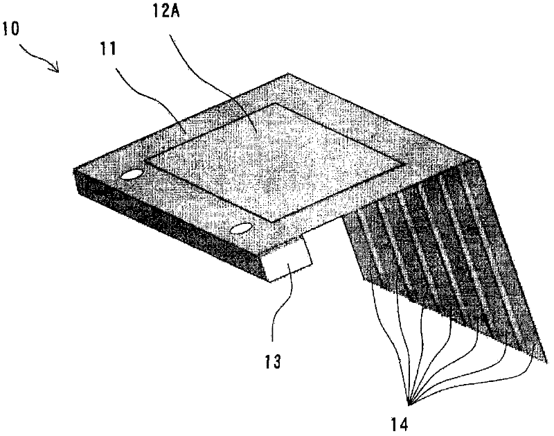
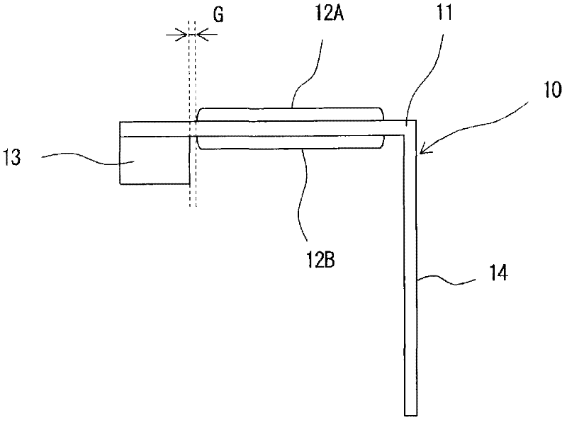
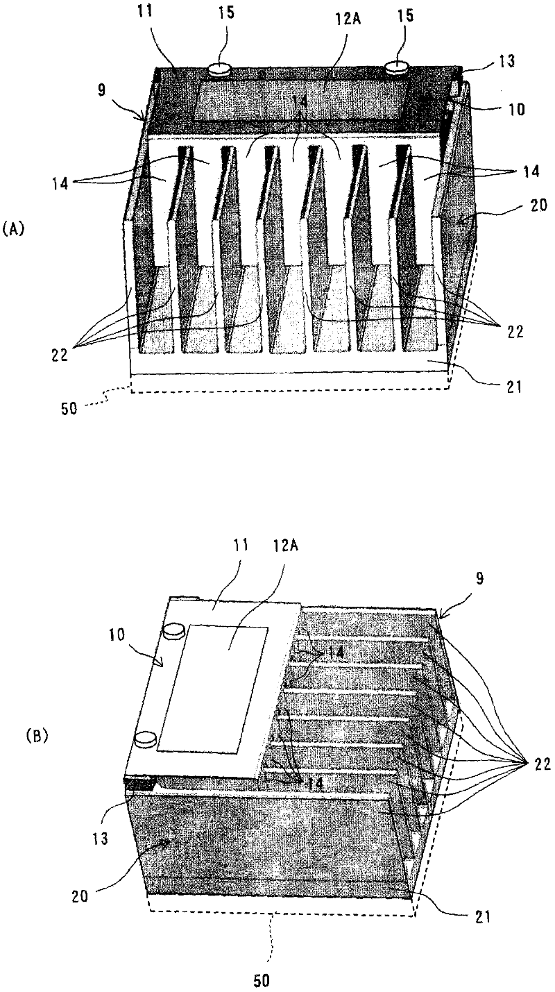
[0120] First, in order to compare the air blowing capability of the piezoelectric fan 30 as a modification of the piezoelectric fan 10 with the air blowing capability of the piezoelectric fan 301 of the present embodiment, the configuration of the piezoelect...


PUM


Abstract

The present invention provides a piezoelectric fan with which the air-moving performance of a vibrating plate is increased and thereby the cooling performance is improved, and also provide a cooling device including the piezoelectric fan. The piezoelectric fan includes reinforcing plates of a stainless steel that increase the rigidity of a portion of the vibrating plate corresponding to a gap between a piezoelectric element and a fixing plate. First ends of the reinforcing plates are attached to portions of the vibrating plate on both sides of piezoelectric elements in the width direction, and second ends of the reinforcing plates are attached to a fixed end of the vibrating plate such that the second ends and the fixing plate sandwich the fixed end of the vibrating plate therebetween and such that the reinforcing plates extend over the gap. The reinforcing plates prevent vibration of the portion of the vibrating plate corresponding to the gap, prevent a portion of vibration energy generated by expansion and contraction of the piezoelectric elements from being consumed in the portion corresponding to the gap, and increase the amplitude of the vibration of blade ends.

Description

technical field [0001] The present invention relates to a piezoelectric fan that emits hot air from the vicinity of a heat radiator, and a cooling device using the piezoelectric fan. Background technique [0002] In recent electronic equipment, with the development of miniaturization of equipment main bodies and high-density mounting of components, heat dissipation measures inside equipment have become a problem. For example, in a personal computer, the size of the main body of the device is getting smaller, and the CPU is getting faster in order to improve the information processing performance. Therefore, the inside of the electronic device becomes an environment in which the high-density mounting of components reduces the ventilation inside the electronic device, and on the other hand, the heat generation amount of the CPU, which is a heat generating body, increases. Therefore, in this environment, it is an important issue to suppress the temperature rise of the CPU by r...

Claims


Application Information

Patent Timeline
Patent Type & Authority Applications(China)
IPC IPC(8): F04B45/047H01L41/08H01L23/467
CPCH01L41/0926H01L23/467F04F7/00H01L41/094H01L23/3672H01L2924/0002H10N30/2042H01L2924/00
Inventor 田中伸拓和田宽昭
Owner MURATA MFG CO LTD
Why Eureka
Try Eureka