Pipe joint

A technology for pipe joints and covers, applied in the field of pipe joints

Inactive Publication Date: 2011-09-21
BRIDGESTONE CORP
View PDF6 Cites 4 Cited by
  • Summary
  • Abstract
  • Description
  • Claims
  • Application Information

AI Technical Summary

Problems solved by technology

[0003] However, in such a pipe joint, even without using a special tool, it is possible for the opening ring to be pushed toward the locking ring side due to, for example, a sleeve or a protective sleeve provided on the outer peripheral portion of the pipe, thereby releasing the lock ring pair. tube bite

Method used


Image

  • Pipe joint
  • Pipe joint
  • Pipe joint

Examples


Embodiment Construction

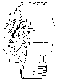
[0041] Below, based on Figure 1 to Figure 4 One embodiment of the present invention will be described.

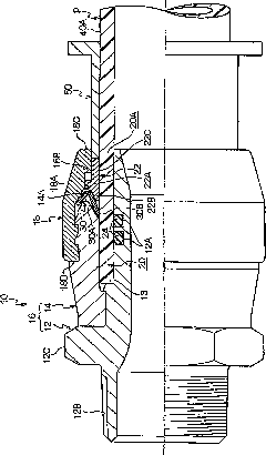
[0042] figure 1 , represents the state after the pipe fitting in one embodiment of the present invention joins the pipe. figure 2 expressed in figure 1 The state where the tool is inserted into the fitting is shown.

[0043]Such as figure 1 and figure 2 As shown, the joint body 16 of the pipe joint 10 is composed of a tubular main body portion 12 and a tubular middle portion 14 sleeved outside the main body portion 12 . In addition, the pipe joint 10 includes a tubular cover body 18 that is sleeved on the outside of the middle part 14. Between the middle part 14, the cover body 18 and the main body part 12, a pipe P (for example, a polybutylene pipe) as a pipe body is formed to be inserted. The insertion hole 20.

[0044] A lock ring 30 for holding the pipe P in the insertion hole 20 is arranged inside the cover body 18 . The cross section of the lock ring 30 is ...


PUM


Abstract

The invention provides a pipe joint, comprising: a cylindrical joint body including therein an insertion portion for receiving insertion of a pipe; a cover which is mounted on the outer surface of the joint body in the vicinity of the side of a pipe insertion opening; a sealing element which is disposed between the pipe inserted into the insertion portion and the joint body; an annular member which is arranged in a position closer to the side of the cover than the sealing element in the axial direction of the joint body and provided with a claw portion locked with the outer peripheral surface of the inserted pipe to hold the pipe, wherein the calibre of the annular member is expandable; a supporting portion which is arranged between the sealing element and the annular member; and a housing which is detachably mounted on the outer peripheral portion of the cover, wherein a push-in prevention portion is formed on an end portion of the housing in the vicinity of the side of the pipe insertion opening; and the push-in prevention portion projects from the cover inwards to prevent expansion of the calibre of the annular member.

Description

technical field [0001] The present invention relates to a pipe joint capable of reliably joining and disengaging pipe bodies with simple operations. Background technique [0002] Conventionally, pipe joints capable of reliably joining and disengaging pipe bodies with simple operations are known (see, for example, JP-A-2006-316877). In this pipe joint, the opening ring and the locking ring are covered by the cover body, and by inserting a cylindrical tool into the gap between the cover body and the pipe, the opening ring is pushed into the locking ring side and the locking ring is The caliber of the tube is enlarged to enable the tube to be disengaged. [0003] However, in such a pipe joint, even without using a special tool, it is possible for the opening ring to be pushed toward the locking ring side due to, for example, a sleeve, a protective sleeve, etc. provided on the outer peripheral portion of the pipe, thereby releasing the lock ring pair. The bite of the tube. C...

Claims


Application Information

Patent Timeline
Patent Type & Authority Applications(China)
IPC IPC(8): F16L21/08F16L21/035F16L15/08F16L47/12F16L47/16
Inventor 长山友久樱田秋能
Owner BRIDGESTONE CORP
Why Eureka
Try Eureka