Control unit provided with locking system for controlling shafts

A control unit and locking technology, applied in the field of component assembly, can solve problems such as difficulty in vehicle maintenance, and achieve the effect of long service life

Active Publication Date: 2011-09-21
APTIV TECH LTD
View PDF4 Cites 2 Cited by
  • Summary
  • Abstract
  • Description
  • Claims
  • Application Information

AI Technical Summary

Problems solved by technology

In this case the specific factory tool is very expensive and since it does not remain on the vehicle subsequent repairs of the vehicle are also difficult as the repairman has to reassemble the unit without tools

Method used


Image

  • Control unit provided with locking system for controlling shafts
  • Control unit provided with locking system for controlling shafts
  • Control unit provided with locking system for controlling shafts

Examples


Embodiment Construction

[0021] The invention will now be described by way of example with reference to the accompanying drawings.

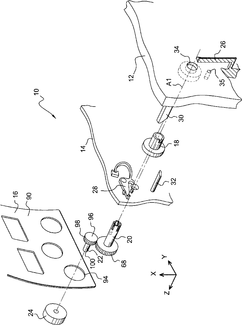
[0022] In a non-limiting manner, the present description is described in a system of vertical axes X-Y-Z such that the assembly axis Z is oriented from "inside" to "outside" as figure 1 shown.

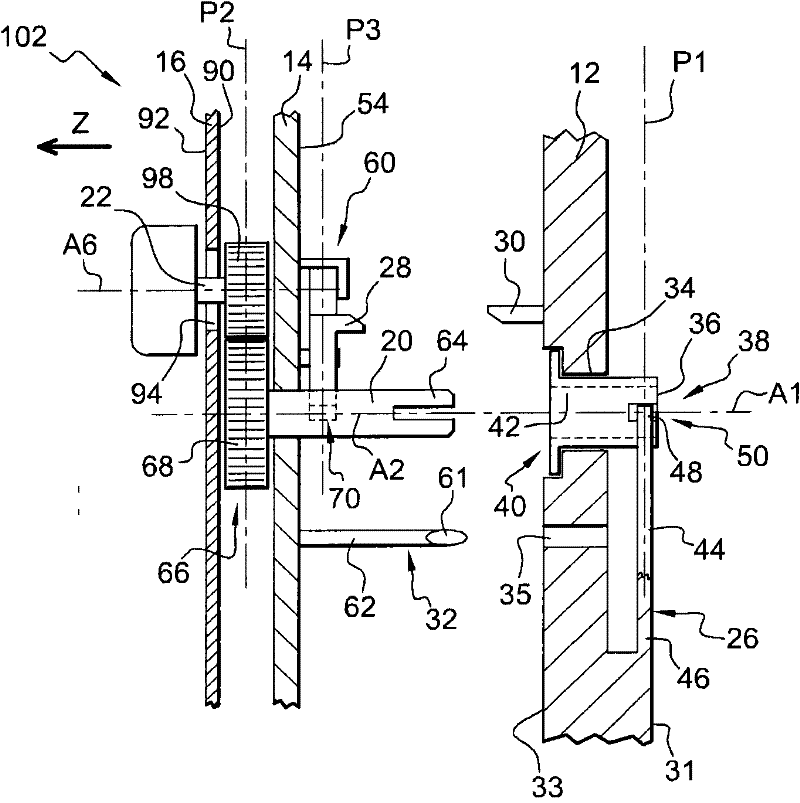
[0023] The control unit 10 of a vehicle air conditioning system with mechanical control (not shown) comprises, along an assembly axis Z from the inside to the outside, a stack of a base body 12, an intermediate panel 14 and a trim panel 16 substantially parallel to the main plane X-Y.

[0024] The control unit 10 is also provided with three shafts 18, 20, 22 oriented perpendicular to the main plane X-Y and extending along their respective axes parallel to the assembly axis Z, and when rotated co-operate. The inner shaft 18 actuates the mechanical control and is rotatably mounted relative to the base body 12 . The intermediate shaft 20 is rotatably mounted relative to the inter...


PUM


Abstract

The invention relates to a control unit, in particular to a control unit for a vehicle air-conditioning system. The control unit comprises a first panel and a second panel assembled along an assembly axis, wherein the first panel is provided with a first shaft, the second panel is provided with a second shaft, and the first shaft and the second shaft are rotationally connected after the panels are assembled. Moreover, in order to assemble conveniently, the second panel is provided with a locking device for fixing the second shaft. The first panel is provided with an unlocking device mutually matched with the locking device, so that the locking device is switched from a locking state to an unlocking state; and the mutual match is realized when the assembly of the panels is finished.

Description

technical field [0001] The invention relates to the assembly of components of a control unit, in particular for a motor vehicle air conditioning system. Background technique [0002] A control unit for a motor vehicle air conditioning system has a trim panel serving as a user interface and includes adjustment buttons for at least one of temperature, speed and direction of air. The decorative panel is fixed to the middle panel, and the middle panel is fixed to the base body. The control axes corresponding to the different possible adjustments are passed through. Each adjustment button is coupled to its corresponding control shaft. [0003] The assembly of the unit is carried out in stages, the first being the vertical approach and subsequent fixing of the trim panel pre-assembled with the adjustment buttons on the middle panel. Subsequently, the assembly thus formed is mounted "blindly" on said base body. It is critical that the shafts not rotate during assembly so that t...

Claims


Application Information

Patent Timeline
IPC IPC(8): F24F11/00
Inventor V·伊斯奎尔多R·蔡劳克斯
Owner APTIV TECH LTD
Why Eureka
Try Eureka