Method for discriminating track distance of compact disc
A technology of optical disc and track distance, which is applied to the recording/reproducing by optical method, optical recording head, beam guiding device, etc., and can solve the problems of long moving distance, inability of the optical head 140 to reach the target position quickly, and influence, etc.
- Summary
- Abstract
- Description
- Claims
- Application Information
AI Technical Summary
Problems solved by technology
Method used
Image
Examples
no. 1 example
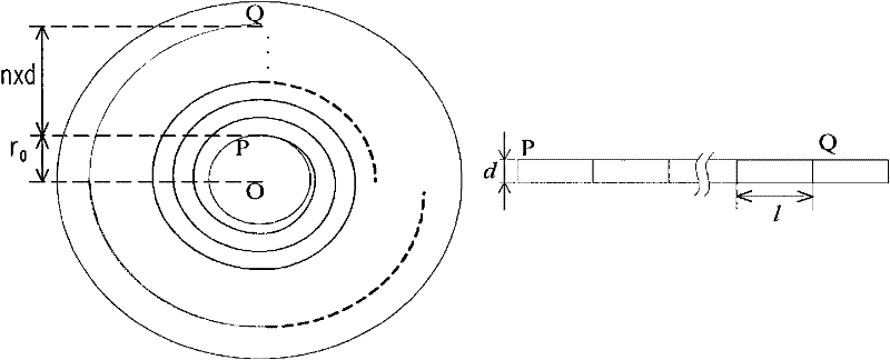
[0056] Please refer to figure 2 , figure 2 It is a schematic diagram of a disc track according to the first embodiment of the present invention. O is the center position of the optical disc, P is the initial position of the track, Q is a track of the optical disc, n is the number of tracks between the initial track and track Q, and d is the track pitch. The distance between positions O and P is r 0 , the distance between positions P and Q can be represented by n×d. The track of the optical disc is a spiral track formed by connecting multiple data sectors. Will figure 2 The left track unfolded into a straight line would look like figure 2 As shown in the figure on the right, the data track is like a data strip composed of rectangular data segments, and the length of each data segment is l.
[0057] Each data sector has a data sector address, and the data sector address is coded progressively from the inner track to the outer track of the optical disc. Therefore, the ...
no. 2 example
[0065] Ideally, the geometric center and the rotation center of the optical disc should be located at the same point. When the spindle motor rotates the optical disc, the track area of the optical disc will rotate around the center of the optical disc. However, when there is a deviation in the manufacturing process of the optical disc, the orbital center and the geometric center of the optical disc will not be located at the same point, which is called eccentricity. When the axis that passes through the center of the disc and is parallel to the screw of the optical drive and the axis that passes through the center of the objective lens and is parallel to the screw of the optical drive are not coincident, we call it a de-center. When an eccentric optical disk or an axis-offset mechanism rotates, its orbit will have a radial upward movement component relative to the optical head. Therefore, the optical head at a fixed position will detect the cross-track signal, and the track ...
no. 3 example
[0080] Since the disc address to be read will be affected by two factors, the track gauge and the degree of eccentricity of the disc, such as Figure 10 shown. Figure 10 It is a test schematic diagram of disc T and disc S with two different track gauges and different eccentricity according to the third embodiment of the present invention. Disc S is a standard disc without eccentricity, and disc T is a disc with eccentricity K in the cross-track direction. Using the same reading distance X to read the disc T and the disc S, in the disc S, the distance between the locking rail position and the axis center of the spindle motor 12 can be expressed as R 0 +Ns×Ds; in the disc T, the distance between the locking rail position and the axis center of the spindle motor 12 can be expressed as R 0 +K+Nt×Dt, where R 0 Indicates the distance between the shaft center of the spindle motor 12 of the standard disc S and the inner side of the track area, Ns indicates the number of tracks rea...
PUM
 Abstract
Description
Claims
Application Information
 - R&D
- Intellectual Property
- Life Sciences
- Materials
- Tech Scout
- Unparalleled Data Quality
- Higher Quality Content
- 60% Fewer Hallucinations
Browse by: Latest US Patents, China's latest patents, Technical Efficacy Thesaurus, Application Domain, Technology Topic, Popular Technical Reports.
© 2025 PatSnap. All rights reserved.Legal|Privacy policy|Modern Slavery Act Transparency Statement|Sitemap|About US| Contact US: help@patsnap.com


