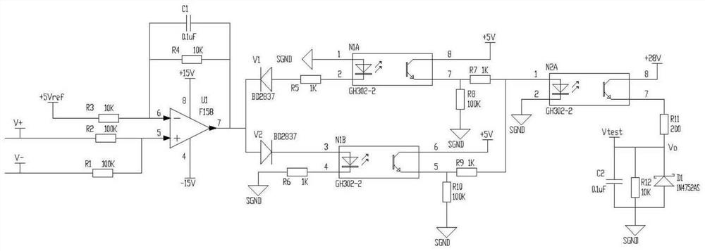
An acceleration sensor self-test circuit
A technology of acceleration sensor and self-test circuit, applied in the direction of speed/acceleration/shock measurement, test/calibration of speed/acceleration/shock measurement equipment, instruments, etc. Core online self-check and other issues
- Summary
- Abstract
- Description
- Claims
- Application Information
AI Technical Summary
Problems solved by technology
Method used
Image
Examples
Embodiment Construction
[0012] The present invention will be described in further detail below. refer to figure 1 , an acceleration sensor self-test circuit, including a series operation circuit, a self-test drive circuit and a self-test output circuit, the operation circuit is composed of an operational amplifier U1, resistors R1, R2, R3, R4, and a capacitor C1; the self-test drive circuit consists of Photocouplers N1A, N1B, switching diodes V1, V2, resistors R5, R6, R7, R8, R9, R10; the self-test output circuit consists of adjusting diodes D1, N2A, resistors R11, R12, and capacitor C2.
[0013] The 4 pins of the operational amplifier U1 are connected to -15V, the 8 pins are connected to +15V, the 5 pins are connected to the right pin of R1 and the right pin of R2, and the 6 pins are connected to the right pin of R3, the left pin of R4 and the left tube of C1 Pin, pin 7 is connected to the right pin of R4 and the right pin of C1; the left pin of the resistor R1 is connected to the V- pin of the acc...
PUM
 Abstract
Description
Claims
Application Information
 - R&D
- Intellectual Property
- Life Sciences
- Materials
- Tech Scout
- Unparalleled Data Quality
- Higher Quality Content
- 60% Fewer Hallucinations
Browse by: Latest US Patents, China's latest patents, Technical Efficacy Thesaurus, Application Domain, Technology Topic, Popular Technical Reports.
© 2025 PatSnap. All rights reserved.Legal|Privacy policy|Modern Slavery Act Transparency Statement|Sitemap|About US| Contact US: help@patsnap.com

