Cable joint monitoring system based on multi-parameter sensing explosion-proof box

A cable joint and monitoring system technology, applied in the direction of cable joints, cable installation, cable installation devices, etc., can solve problems such as contact resistance increase, joint burnout, secondary accidents, etc., to avoid fire, ensure safety, Strong field applicability

Inactive Publication Date: 2021-06-11
STATE GRID JIANGSU ELECTRIC POWER CO ELECTRIC POWER RES INST +2
View PDF4 Cites 2 Cited by
  • Summary
  • Abstract
  • Description
  • Claims
  • Application Information

AI Technical Summary

Problems solved by technology

After the cable is used for a long time, its joints are prone to oxidation due to a long period of high current load, resulting in an increase in the contact resistance at the cable connection point. When a large current passes through, it is easy to cause the joints to burn through due to overheating.
The cable intermediate joint is the weakest link in the power cable line. When a fault occurs and a fire and explosion accident occurs, it will not only burn the adjacent cable, but also damage other surrounding equipment, causing secondary accidents, and bringing serious problems to the safe operation of the power grid. question

Method used


Image

  • Cable joint monitoring system based on multi-parameter sensing explosion-proof box
  • Cable joint monitoring system based on multi-parameter sensing explosion-proof box
  • Cable joint monitoring system based on multi-parameter sensing explosion-proof box

Examples


Embodiment Construction

[0033] Next, the technical solutions in the embodiments of the present invention will be apparent from the embodiment of the present invention, and it is clearly described, and it is understood that the described embodiments are merely embodiments of the present invention, not all of the embodiments.

[0034] It should be noted that when the element is referred to as "fixed to" another element, it can be directly in another element or may also exist. When a component is considered to be "connected" another element, it can be directly connected to another element or may exist simultaneously. The term "vertical", "horizontal", "left", "right", "left", "right", "left", "right", and similar expressions are merely embodiments.

[0035] All techniques and scientific terms used herein are identical to those skilled in the art, unless otherwise defined. The term used herein in the specification of the present invention is intended to describe the embodiments of the specific embodiments, a...


PUM


Abstract

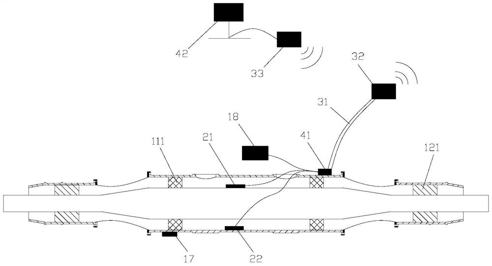
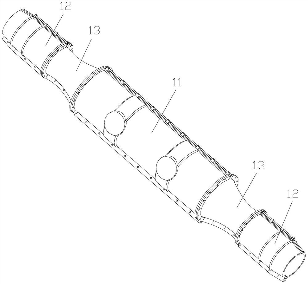
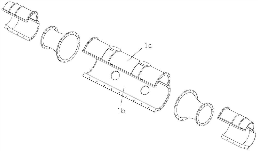
The invention relates to the technical field of cable fault monitoring, in particular to a cable joint monitoring system based on a multi-parameter sensing explosion-proof box. An acquisition module is arranged in the explosion-proof box and is connected with a processing module through a transmission module, and the acquisition module comprises a temperature sensor and a pressure sensor, which are respectively used for acquiring the surface temperature of the cable joint and the pressure in the explosion-proof box; the communication data line is connected with the acquisition modules and the converter, and the wireless transmitter and the wireless receiver are respectively connected with the converter and the upper computer. The explosion-proof box is arranged at a cable joint section to ensure the safety of a cable joint, and the electronic tag and the sensor arranged on the explosion-proof box are matched to monitor the temperature, the pressure and the physical position characteristic quantity of the cable intermediate joint, so the middle box body and the end box body of the fault monitoring explosion-proof box for sensing the multi-parameter state of the joint are connected through the flexible part; therefore, the cable bending device can meet the requirement for the bending environment of on-site cables, and is easy to mount and dismount, convenient to operate and high in on-site applicability.

Description

Technical field [0001] The present invention relates to the field of cable fault monitoring, and more particularly to a cable joint monitoring system based on multi-parameter perceived explosion-proof boxes. Background technique [0002] With the rapid development of urban grid, the power cable has been increasingly widely used in power systems, and the ratio of fire explosion accidents in cable disaster accidents is also increased. In order to alleviate the cable laying and the difficulty of operation, the intermediate joint will be added every other length cable. After the cable is used for a long time, its joint is susceptible to oxidation due to a long period of time, resulting in an increase in contact resistance at the cable connection point, and it is easy to cause the joint due to overheating due to overheating. The intermediate connector of the cable is the weakest link in the power cable line. When a failure causes a fire explosion accident, it will not only burn near t...

Claims


Application Information

Patent Timeline
Patent Type & Authority Applications(China)
IPC IPC(8): H02G15/10H02G1/00H02G1/14H02J13/00G01D21/02
CPCH02G15/10G01D21/02H02G1/00H02G1/14H02J13/00002H02J13/00001H02J13/00032H02J13/00022H02J13/00006
Inventor 李陈莹陈杰胡丽斌谭笑曹京荥张伟刘建军陶风波王永强
Owner STATE GRID JIANGSU ELECTRIC POWER CO ELECTRIC POWER RES INST
Why Eureka
Try Eureka