Electronic camera

A camera, electronic technology, applied in the direction of television, electrical components, color television, etc., can solve problems such as reducing the visual recognition of images

Inactive Publication Date: 2011-09-21
SANYO ELECTRIC CO LTD
View PDF5 Cites 3 Cited by
  • Summary
  • Abstract
  • Description
  • Claims
  • Application Information

AI Technical Summary

Problems solved by technology

[0004] However, in the background art, when the imaging device is tilted and the image is captured in a state where hand shake is not recognized, the recorded image will be an image that is not based on the photographer's point of view, thereby reducing the accuracy of the image. visual identity

Method used


Image

  • Electronic camera
  • Electronic camera
  • Electronic camera

Examples


Embodiment

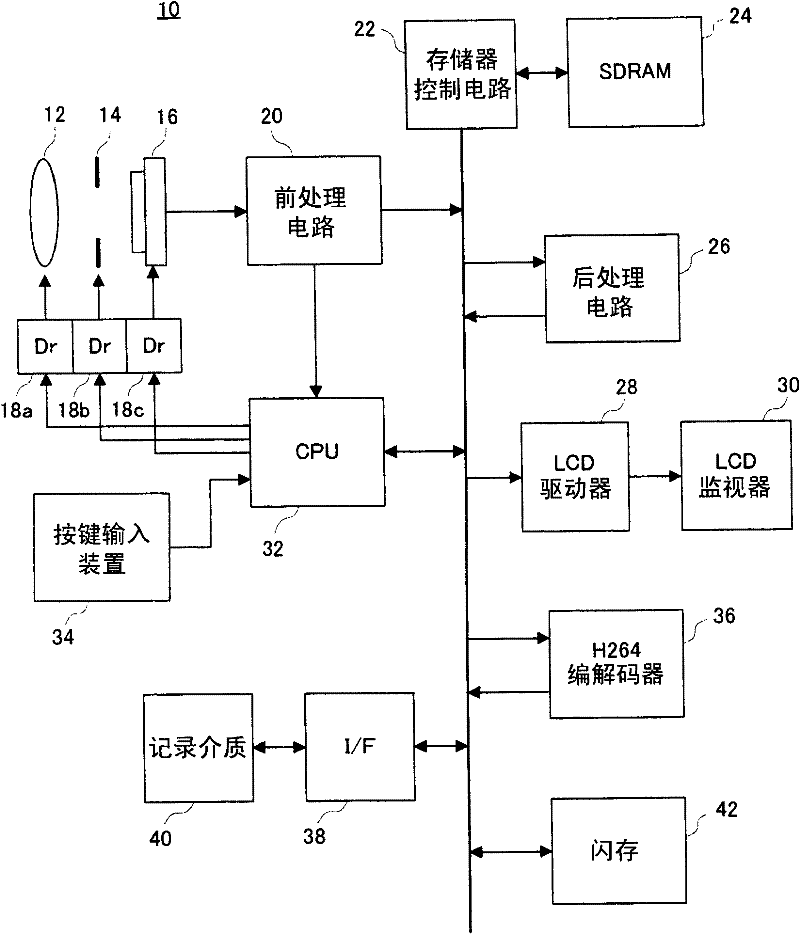
[0038] refer to figure 2 , the digital video camera 10 of this embodiment includes a focus lens 12 and an aperture unit 14 respectively driven by drivers 18a and 18b. The optical image of the subject scene is irradiated onto the imaging surface of the image sensor 16 through these components. In addition, the effective image range of the imaging plane has a resolution of 2560 pixels horizontally x 1600 pixels vertically.

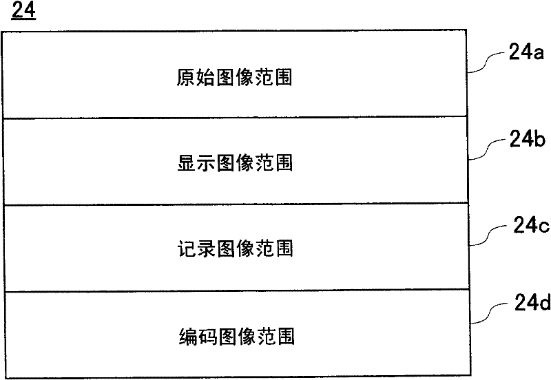
[0039] The digital video camera 10 has SDRAM 24 as a storage device. Each unit constituting the digital video camera 10 executes a write operation for writing data into the SDRAM 24 and a read operation for reading data stored in the SDRAM 24 by issuing an access request to the memory control circuit 22 . In the access request, the distinction between reading (read) and writing (write) and the head address and size of the target data are described.

[0040] When there is a read request to read image data, after an approval signal is returned from the mem...


PUM


Abstract

An electronic camera includes an imaging device. The imaging device outputs a scene image produced on an imaging surface capturing a scene. A rotator performs a rotating process in a direction around an optical axis on the scene image outputted from the imaging device in response to a recording operation. A recorder records the scene image rotated by the rotator on a recording medium. A determiner determines a rotation of the imaging surface in the direction around the optical axis in response to the recording operation. An adjuster adjusts a rotation angle of the rotator to an angle which is different corresponding to a determined result of the determiner. The vision identity of the recording image is increased.

Description

technical field [0001] The present invention relates to an electronic camera, and more particularly, to an electronic camera including an openable and closable monitor section on the side. Background technique [0002] An example of such a device has been disclosed in Patent Document 1. According to the background art, it is known that the motion of the imaging device is detected by using the motion vector obtained by the hand shake detection sensor or the video signal, and based on the motion detection result, the cut-out frame Bn (effective imaging area) is moved within the maximum imaging-capable area to perform Hand shake compensation. [0003] [Patent Document 1] Japanese Patent Laid-Open No. 2008-124787 [0004] However, in the background art, when the imaging device is tilted and the image is captured in a state where hand shake is not recognized, the recorded image will be an image that is not based on the photographer's point of view, thereby reducing the accuracy...

Claims


Application Information

Patent Timeline
Patent Type & Authority Applications(China)
IPC IPC(8): H04N5/225H04N9/04H04N5/77
CPCH04N21/4334H04N9/7904H04N21/42202H04N21/44008H04N21/4402H04N5/772H04N9/7921H04N21/4223H04N5/23248H04N23/68
Inventor 新保稔康黑川光章
Owner SANYO ELECTRIC CO LTD
Why Eureka
Try Eureka