Swirling air intake centrifugal fan
A centrifugal fan and air inlet technology, which is applied in the direction of mechanical equipment, radial flow pumps, machines/engines, etc., can solve the problems of unfavorable environmental protection, large air intake resistance, and loud noise, so as to improve the air intake effect and increase the The fan flow rate and the effect of improving the total pressure efficiency
- Summary
- Abstract
- Description
- Claims
- Application Information
AI Technical Summary
Problems solved by technology
Method used
Image
Examples
Embodiment 1
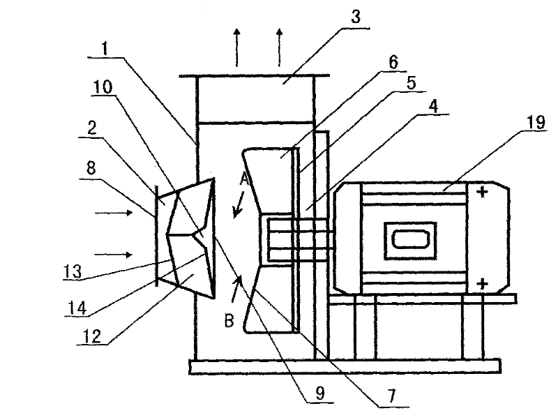
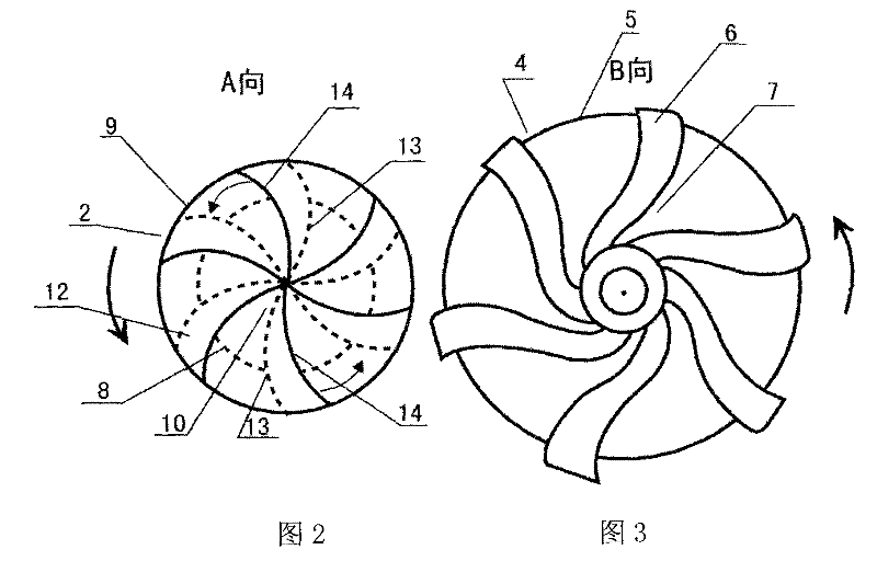
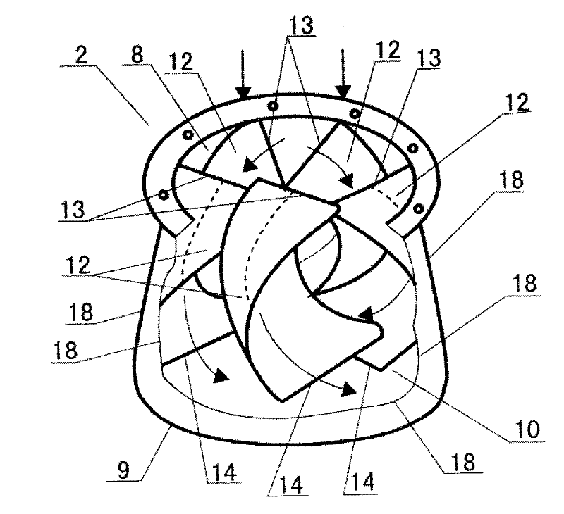
[0047] Embodiment 1, reference figure 1 , figure 2 , image 3 , Figure 4 , Figure 5 , a swirling air inlet centrifugal fan, comprising a casing 1, an expanded casing air inlet 2, a casing air outlet 3, a back flow fan impeller 4, a rear side impeller blade disc 5 (no front impeller blade disc, No air inlet in the middle of the impeller), three-wall structure impeller blade 6, impeller blade axial inlet 7 (negative pressure gap), casing air inlet inlet 8, casing air inlet outlet 9, and casing air inlet 2 is equipped with a rotary The flow inducer 10 and the swirl inducer 10 are composed of five curved baffle blades 12, each baffle blade 12 is connected to each other in the axial front and radial front end, and the radial rear end of the baffle blade 12 is connected to the air inlet of the casing 2. The side walls are connected. The baffle blade 12 is axially inclined from front to rear along the circumferential direction against the impeller. 12. The outlet 14 of the ax...
Embodiment 2
[0053] Embodiment 2, refer to Image 6 , Figure 7 , Figure 8 , Figure 9 , This example is basically the same as Example 1, except that the impeller of this example is provided with an air inlet 15 in the middle of the impeller and a radial inlet 16 of the impeller blades. The second difference is that the impeller blades of this example become forward-inclined, and the axial inlet 7 of the impeller blades also become forward-inclined.
[0054] When this example is working, the rotating airflow at the outlet of the air inlet of the casing will enter the inner flow channel of the impeller tangentially from two parts of the radial inlet 16 of the impeller blade and the axial inlet 7 of the impeller blade of the air inlet in the middle of the impeller, so that the impeller can be sucked in more. More air volume for processing. Since the impeller blades and the axial inlet of the impeller blades in this example are both forward-inclined, during operation, the swirling airflo...
Embodiment 3
[0056] Embodiment 3, refer to Figure 10 , this example is basically the same as Example 2, the difference is that the impeller 4 of this example is a synchronous backflow ventilation compressor impeller, the whole impeller is a conical cylinder structure, the impeller blades are a synchronous backflow fan impeller blade structure, and the impeller blades are provided with There are synchronous diversion supercharger 17 and synchronous downstream inlet 7. The axial front side of the impeller is also provided with the air inlet 15 in the middle of the impeller, the radial (inclined) inlet 16 of the impeller blade is provided, and the axial inlet 7 of the impeller blade (synchronous downstream inlet) is provided.
[0057] When this example is working, the rotation direction of the airflow at the air inlet outlet 9 of the casing is opposite to that of the impeller, and the impeller sucks gas through the air inlet 15 in the middle of the impeller, the radial inlet 16 of the impell...
PUM
 Abstract
Description
Claims
Application Information
 - R&D
- Intellectual Property
- Life Sciences
- Materials
- Tech Scout
- Unparalleled Data Quality
- Higher Quality Content
- 60% Fewer Hallucinations
Browse by: Latest US Patents, China's latest patents, Technical Efficacy Thesaurus, Application Domain, Technology Topic, Popular Technical Reports.
© 2025 PatSnap. All rights reserved.Legal|Privacy policy|Modern Slavery Act Transparency Statement|Sitemap|About US| Contact US: help@patsnap.com


