Tripping device, breaker and defencive function extension method of breaker

A technology of tripping device and circuit breaker, applied in the direction of protection switch operation/release mechanism, etc., can solve problems such as mutual interference, and achieve the effect of ensuring safety

Active Publication Date: 2013-08-14
CHANGSHU SWITCHGEAR MFG CO LTD (FORMER CHANGSHU SWITCHGEAR PLANT)
View PDF3 Cites 0 Cited by
  • Summary
  • Abstract
  • Description
  • Claims
  • Application Information

AI Technical Summary

Problems solved by technology

[0006] The technical problem to be solved by the present invention is to overcome the problem of mutual interference existing in the sharing of existing intelligent tripping devices and self-powered quick tripping devices, and to provide a method that can realize multiple protections without mutual interference between multiple protections, and reliably guarantee Trip device for power system safety

Method used


Image

  • Tripping device, breaker and defencive function extension method of breaker
  • Tripping device, breaker and defencive function extension method of breaker
  • Tripping device, breaker and defencive function extension method of breaker

Examples


Embodiment 1

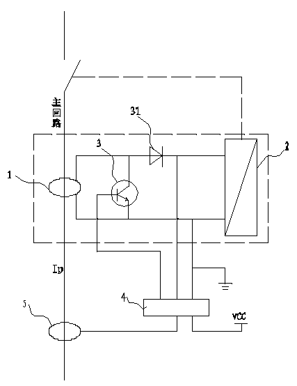
[0027] like figure 2 As shown, in this embodiment, the first tripping execution unit is the most commonly used magnetic flux converter 2, and the magnetic flux converter 2 receives the signal of the first tripping drive unit connected to it to trigger the contact arc extinguishing system Or contact action, shut off the main circuit. The first tripping drive unit is a self-powered tripping drive unit 1 . The self-powered tripping drive unit 1 in the present invention may adopt the current transformer in US Pat. No. 6,034,858A, or other similar technical solutions. like figure 2 As shown, in the loop formed by the self-powered tripping drive unit 1 and the flux converter 2, a switch tube 3 connected in parallel with the flux converter 2 is connected, and the control terminal of the switch tube 3 is connected to a circuit using an external power supply. Smart trip unit connection. The intelligent release includes a detection unit 5 that detects changes in the main circuit c...

Embodiment 2

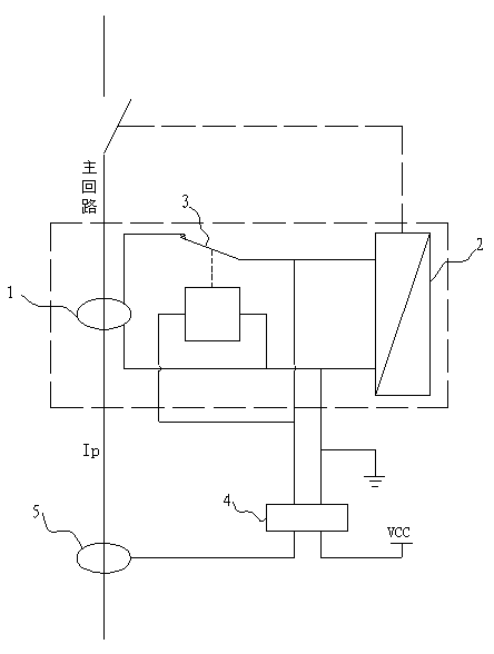
[0029] like image 3 As shown, in this embodiment, in the loop formed by the self-powered tripping drive unit 1 and the flux converter 2 , a relay 3 is connected in series, and the input end of the relay 3 is connected to the intelligent controller 4 . Other parts are the same as those in Embodiment 1, and will not be repeated here. When the intelligent controller 4 can supply the magnetic flux converter 2 normally, it can provide a control current to the relay 3 at the same time, so that the output circuit of the relay 3 is in the off state. At this time, the self-powered tripping drive unit 1 and the magnetic flux conversion The circuit formed by the circuit breaker 2 is disconnected, and the self-powered trip drive unit 1 cannot provide tripping power to the flux converter 2. The intelligent tripper composed of the detection unit 5, the intelligent controller 4 and the flux converter 2 bear. When the intelligent release cannot work effectively, such as when the extern...


PUM


Abstract

The invention discloses a tripping device applied to a low-voltage circuit breaker. The tripping device comprises a first tripping executing unit and a first tripping driving unit. The first tripping driving unit is electrically connected with the first tripping executing unit; and a circuit formed by the first tripping driving unit and the first tripping executing unit is connected with a shielding unit, and the shielding unit can be controlled by an external signal to make the circuit be switched off or switched on. The invention further discloses a circuit breaker comprising the tripping device disclosed by the invention and a protection function expansion method of the circuit breaker. Compared with the prior art, the invention can realize multiple protection without interference one another.

Description

technical field [0001] The invention relates to a tripping device, in particular to a tripping device for a low-voltage circuit breaker, and belongs to the field of low-voltage electrical appliances. Background technique [0002] As we all know, low-voltage circuit breakers are used to break and connect circuits infrequently. One of its most important functions is to cut off the power supply in the event of a short-circuit fault in the circuit to protect the safety of lines, equipment and personnel. A circuit breaker is usually composed of a contact arc extinguishing system, a tripping actuator and a tripping drive unit. The function of the contact arc extinguishing system is to rely on the opening and closing of the contacts to connect and break the circuit; The opening and closing of the contacts provides the driving force, such as the most common flux converter; the tripping drive unit monitors the changes in the operating parameters of the circuit, and sends an opening c...

Claims


Application Information

Patent Timeline
Patent Type & Authority Patents(China)
IPC IPC(8): H01H71/12
Inventor 刘洪武何艳峰管瑞良
Owner CHANGSHU SWITCHGEAR MFG CO LTD (FORMER CHANGSHU SWITCHGEAR PLANT)
Why Eureka
Try Eureka