Fuel supply part structure of vehicle

A supply part and fuel technology, applied to the arrangement combined with the internal combustion engine fuel supply, vehicle components, power devices, etc., can solve the problems of increasing the cost of clips, rust, and long tethers, etc., to improve operability and reduce Cost, the effect of avoiding rust

Inactive Publication Date: 2011-10-05
SUZUKI MOTOR CORP
View PDF9 Cites 3 Cited by
  • Summary
  • Abstract
  • Description
  • Claims
  • Application Information

AI Technical Summary

Problems solved by technology

However, this operation cannot be performed due to the closed cross-section of the frame F, so that the only way to remove the clip is to damage the hook
Therefore, when the other end portion 5B of the tether 5 is attached to the frame F on the vehicle body side, a new clip is required, which increases the cost of the clip
[0006] In addition, water ma

Method used


Image

  • Fuel supply part structure of vehicle
  • Fuel supply part structure of vehicle
  • Fuel supply part structure of vehicle

Examples


Embodiment Construction

[0040] Embodiments of the present invention will now be described with reference to the accompanying drawings.

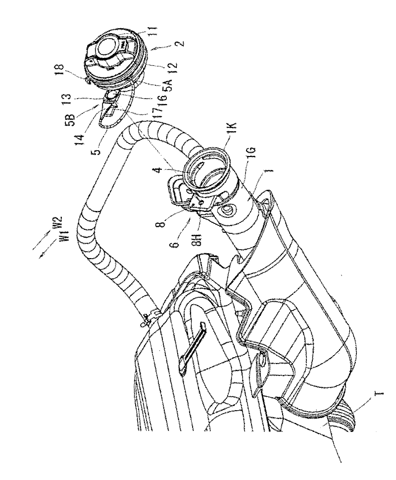
[0041] figure 1 A fuel supply portion structure of a truck-type motor vehicle (corresponding to a vehicle) provided with a fuel filler neck 1 and a resin-made fuel filler cap 2 is shown. The fuel filler neck 1 is connected to the fuel tank T, and is attached to the vehicle body in a state where a portion near the filler hole 1K is exposed. A fuel filler cap 2 is mounted to a filler hole 1K of a fuel filler neck 1 .

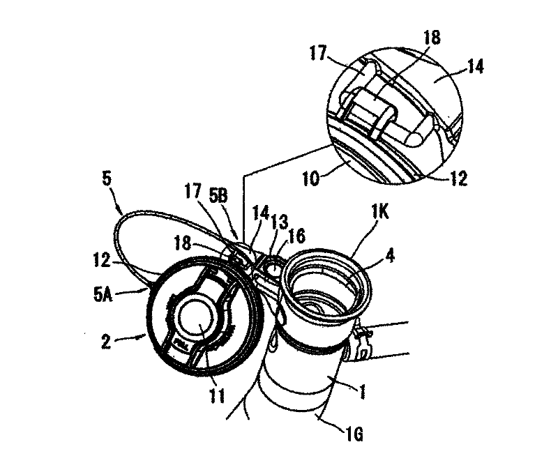
[0042] The fuel filler neck 1 extends obliquely upward laterally from the fuel tank T side, and the filler hole 1K of the fuel filler neck 1 is inclined in a state of being located on the upper side as it goes toward the inner side W1 in the vehicle width direction. The hole end of the fuel filler neck 1 is formed with an internal threaded portion 4, which is threadedly engaged with the external threaded portion 3 of the fuel filler cap 2 (refer to ...


PUM


Abstract

Provided is a fuel supply part structure of a vehicle. The fuel supply part structure comprises a fuel charging port (1) connected with a fuel tank (T) and connected with a vehicle body when a part near a charging opening (1K) is exposed to the outside; and a fuel discharging port cover (2) installed on the charging opening (1K) of the fuel charging port (1) and connected with one end (5A) of a tightening rope (5). A support (6) is connected to the external surface (1G) of the fuel charging port (1) at a place near the charging opening (1K), and the other end (5B) of the tightening rope (5) is attached to the support (6).

Description

technical field [0001] The present invention relates to a fuel supply portion structure for a vehicle, wherein the structure includes: a fuel filler neck connected to a fuel tank and attached to a vehicle in a state where a portion near a filler hole is exposed. a body; and a fuel filler cap mounted to the filler hole of the fuel filler neck and one end of a tether connected to the fuel filler cap. Background technique [0002] like Figure 11 (a) and Figure 11 As shown in (b), for a truck type vehicle, the fuel filler neck 1 connected to the fuel tank T is attached to the vehicle body in a state where a part of the filler hole is exposed. [0003] Conventionally, one end 5A of the tether 5 is connected to the fuel filler cap 2 and the other end 5B of the tether 5 is attached to the neck bracket 8 which will be positioned in the up and down direction of the fuel filler neck 1 The upper middle section is connected to the car body. like Figure 11 As shown in (c), in some s...

Claims


Application Information

Patent Timeline
IPC IPC(8): B60K15/04
CPCB60K15/0406
Inventor 榛村浩希
Owner SUZUKI MOTOR CORP
Why Eureka
Try Eureka