Cylinder control valve for down-the-hole drill

A technology of cylinder control and down-the-hole drilling, which is applied in the direction of valve details, safety valves, balance valves, etc., can solve the problems of pulling the handle, inaccurate positioning, and affecting the flexibility of valve core rotation and operation, so as to ensure stability Effect

Inactive Publication Date: 2011-10-05
迟利民
View PDF5 Cites 0 Cited by
  • Summary
  • Abstract
  • Description
  • Claims
  • Application Information

AI Technical Summary

Problems solved by technology

[0002] The existing down-the-hole drilling cylinder control valve cannot control the dual air chambers of the cylinder to release pressure at the same time, and the drill rod is always working under pressure. The operation requirements are extremely strict. Once the operation is careless, the drilling rig is easy to be overturned, resulting in production safety accidents
[0003] On the other hand, after the existing down-the-hole drilling cylinder control valve is filled with high-pressure gas, the valve core and the valve cover are too tight, which affects the flexibility of the valve core rotation operation, and it is very difficult to pull the handle.
[0004] In the third aspect, when the spool needs to be stopped, since there is no damping mechanism, the spool is prone to undesired free rotation after the handle is released, and the positioning is inaccurate

Method used


Image

  • Cylinder control valve for down-the-hole drill
  • Cylinder control valve for down-the-hole drill
  • Cylinder control valve for down-the-hole drill

Examples


Embodiment Construction

[0024] The present invention will be further described below in conjunction with the accompanying drawings and examples.

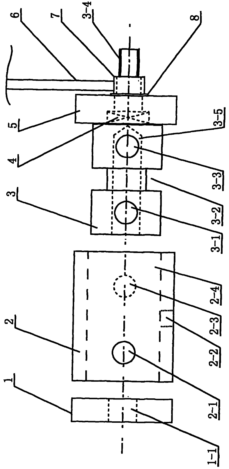
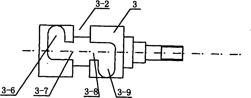
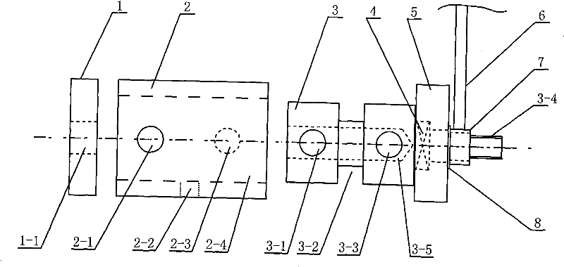
[0025] Such as figure 1 As shown, this embodiment includes a valve body 2 with a valve body center hole 2-4, a valve core 3 tightly fitted and rotatably installed in the valve body center hole 2-4, and the valve core 3 has an open end The spool center hole 3-5 that the other end is closed.

[0026] It also includes a valve seat 1 connected to the inner end of the valve body 2 and a valve cover 5 connected to the outer end of the valve body 2 . The outer end of the valve core 3 passes through the valve cover 5 and is connected with a handle seat 7 with a handle 6 . The outermost end of the spool 3 is a threaded section 3-4 for installing an adjusting nut. A thrust roller bearing 4 is installed in the valve cover 5 , and the inner end surface of the thrust roller bearing 4 leans against the valve core 3 . A damping gasket 8 is also installed on the outer...


PUM


Abstract

The invention discloses a cylinder control valve for a down-the-hole drill. A valve core (3) is at a position where a first air outlet hole (3-1) and a second air outlet hole (3-3) of the valve core (3) are sealed by a valve body (2) simultaneously; and two arc-shaped air leakage grooves on the valve core (3) are communicated with a first air hole (2-1) and a second air hole (2-3) on the valve body respectively and are communicated with an air leakage hole (2-2) through an annular air leakage groove (3-2). By the cylinder control valve, the aim that air pressure in air inlet and outlet cavities of a cylinder is balanced with outside is fulfilled, the drill can drill downwards due to dead weight, and the problem that the drill is turned over due to reacting force caused by excessive pressurization so as to cause a safety accident in the process of drilling downwards by means of aerodynamic force is solved.

Description

technical field [0001] The invention relates to a cylinder control valve, in particular to a down-the-hole drilling cylinder control valve. Background technique [0002] The existing down-the-hole drilling cylinder control valve cannot control the dual air chambers of the cylinder to release pressure at the same time, and the drill rod is always working under pressure. The operation requirements are extremely strict. Once the operation is careless, the drilling rig is easy to be overturned, resulting in production safety accidents. [0003] On the other hand, after the existing down-the-hole drilling cylinder control valve is filled with high-pressure gas, the valve core and the valve cover are too tightly matched, which affects the flexibility of the valve core rotation operation, and it is very difficult to pull the handle. [0004] Thirdly, when the spool needs to be stopped, since there is no damping mechanism, the spool tends to rotate undesirably after the handle is re...

Claims


Application Information

Patent Timeline
Patent Type & Authority Applications(China)
IPC IPC(8): F16K17/20F16K27/00F16K31/60F16K35/00E21B4/06
Inventor 迟利民迟振亭姜颖
Owner 迟利民
Why Eureka
Try Eureka