Method for determining scanning sequence of reference image pixel points

A scanning sequence and reference image technology, applied in 3D image processing, image communication, image data processing, etc., can solve problems such as DIBR description scanning sequence

Inactive Publication Date: 2011-10-05
SICHUAN PANOVASIC TECH +1
View PDF4 Cites 2 Cited by
  • Summary
  • Abstract
  • Description
  • Claims
  • Application Information

AI Technical Summary

Problems solved by technology

But McMillan did not specify the scanning order in each case for DIBR

Method used


Image

  • Method for determining scanning sequence of reference image pixel points
  • Method for determining scanning sequence of reference image pixel points
  • Method for determining scanning sequence of reference image pixel points

Examples


Embodiment

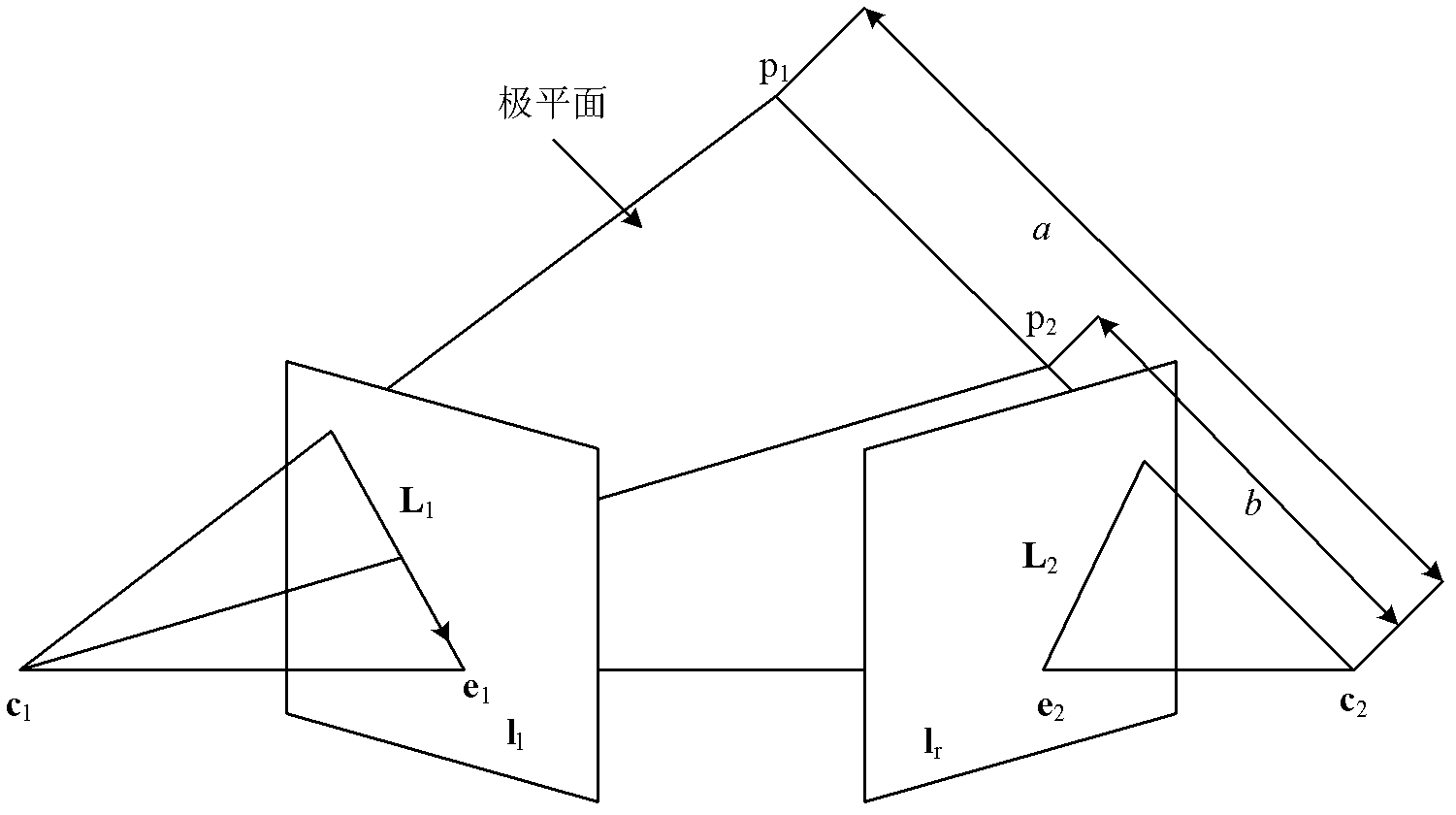
[0045] Such as figure 1 As shown, a, b represent the pixel point p 1 ,p 2 from the virtual camera optical center c 2 distance, and a>b. from figure 1 It can be concluded that: in the reference image I l along the epipolar line L 1 point to the positive pole e 1 When processing the pixels in the reference image, the distance from the virtual camera optical center c 2 far pixel point p 1 Draw first, the nearest pixel point p 2 After drawing, so away from the optical center c 2 Nearest pixel point p 2 The information will cover the distant pixel point p 1 information to establish the correct visibility relationship. if e 1 is a negative pole, then in the reference image I l Pixels are processed along the direction of the epipolar line away from the negative pole.

[0046] Since all pixels that may cause wrinkles can be constrained on polar planes, all polar planes intersect at the baseline, and all epipolar lines intersect at poles. In this way, as long as the pol...

example

[0068] In this example, the "ballet" sequence (image resolution 1024*768) is used for experiments. The video capture system used in this sequence is as follows: Figure 11 As shown, it has 8 cameras, cameras 0, 2, 5, and 7 are placed on the arc with a central angle of 30°, and other cameras are placed on the secant of the arc in turn. The field of view (Field of View, FOV) of the camera is 30°, and the data of this sequence contains the internal parameter matrix K of each camera i and the external parameter matrix [R i | T i ] (0≤i≤7).

[0069] In this example, the image captured by the camera 5 is used as the reference image and the image captured by the virtual camera 4 is used. Among them, the internal parameter matrix K of camera 4 4 and external parameter matrix [R 4 | T 4 ] As shown in formula (5) and formula (6); the internal parameter matrix K of camera 5 5 and external parameter matrix [R 5 | T 5 ] as shown in formula (7) and formula (8).

[0070] ...


PUM


Abstract

The invention discloses a method for determining a scanning sequence of reference image pixel points. In actual application, a right (left) view, namely a target view, is generated by using a reference image as a left (right) view under most conditions; and a baseline is parallel to the reference image. Based on a shading compatible algorithm provided by McMillan, the invention provides the method for determining the scanning sequence of the reference image pixel points in a three-dimensional image transform process. By using the method, the scanning sequence of the reference image pixel points is determined when the baseline is parallel to the reference image plane and optic centers of cameras are on the same horizontal line. The experiments show that an accurate drawing sequence of a target image can be obtained by using the method.

Description

technical field [0001] The invention belongs to the technical field of depth image rendering in a 3D television system, and more specifically relates to a method for determining the scanning order of pixel points of a reference image in a three-dimensional image conversion process. Background technique [0002] Depth-image-based rendering (DIBR) technology is a key technology in 3D TV systems, which has attracted the attention of many research institutions. Traditional 3D video signal transmission needs to transmit two video streams for the left eye and right eye, but the 3D TV system based on DIBR technology only needs to transmit one video stream and the corresponding depth information, which can reduce the transmission bandwidth. [0003] The core step of DIBR technology is three-dimensional image transformation (3d image warping). The 3D image transformation can project the points in the reference image to the 3D space, and then reproject the points in the 3D space onto...

Claims


Application Information

Patent Timeline
Patent Type & Authority Applications(China)
IPC IPC(8): G06T15/20H04N13/00
Inventor 刘然田逢春刘阳鲁国宁许小艳黄扬帆甘平谢辉邰国钦谭迎春刘艳飞张莎
Owner SICHUAN PANOVASIC TECH
Why Eureka
Try Eureka