A Partition Die Compression Forming Method for Lightweight Alloy Thin-wall Curved Surface Parts

A light alloy, compression molding technology, applied in the direction of forming tools, metal processing equipment, manufacturing tools, etc., can solve the problems of large springback, uneven deformation, and inability to solve the problem of wrinkling in light alloy forming at room temperature, and achieve reduction The effect of zoned compression molding wrinkling tendency, reducing the degree of shape asymmetry, and improving the ability to resist instability and wrinkling

Active Publication Date: 2021-06-22
DALIAN UNIV OF TECH
View PDF8 Cites 0 Cited by
  • Summary
  • Abstract
  • Description
  • Claims
  • Application Information

AI Technical Summary

Problems solved by technology

For curved surface parts with large curvature changes and thin wall thickness, such as melon petals of carrying storage tanks, due to the asymmetrical shape of the profile and the large difference in the radius of curvature within the surface, large compressive stress will be generated in the area with a large radius of gyration during molding , causing wrinkling
In addition, the springback of lightweight alloys at room temperature is large, and the dimensional accuracy of thin-walled curved parts is also poor.
Although stretching can solve the problems of large springback and easy wrinkling in the molding of melon petals and thin-walled curved parts such as skins, the stretching is to clamp the two ends of the slab and then stick to the mold. On the one hand, it requires a long transition section to meet the end clamping and surface forming, the material utilization rate is less than 30%, and the material waste is serious; on the other hand, there is a sequence of contact between the slab and the mold, there is serious deformation unevenness, and even cracking leads to the formation can not be completed smoothly
[0004] The existing technology cannot solve the problem of wrinkling in the molding of such thin-walled curved parts

Method used


Image

  • A Partition Die Compression Forming Method for Lightweight Alloy Thin-wall Curved Surface Parts
  • A Partition Die Compression Forming Method for Lightweight Alloy Thin-wall Curved Surface Parts
  • A Partition Die Compression Forming Method for Lightweight Alloy Thin-wall Curved Surface Parts

Examples


Embodiment 1

[0044] Five divisions-30-70-50-aluminum alloy-forming and quenching integration

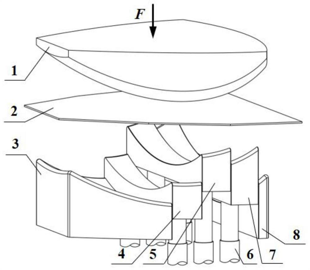
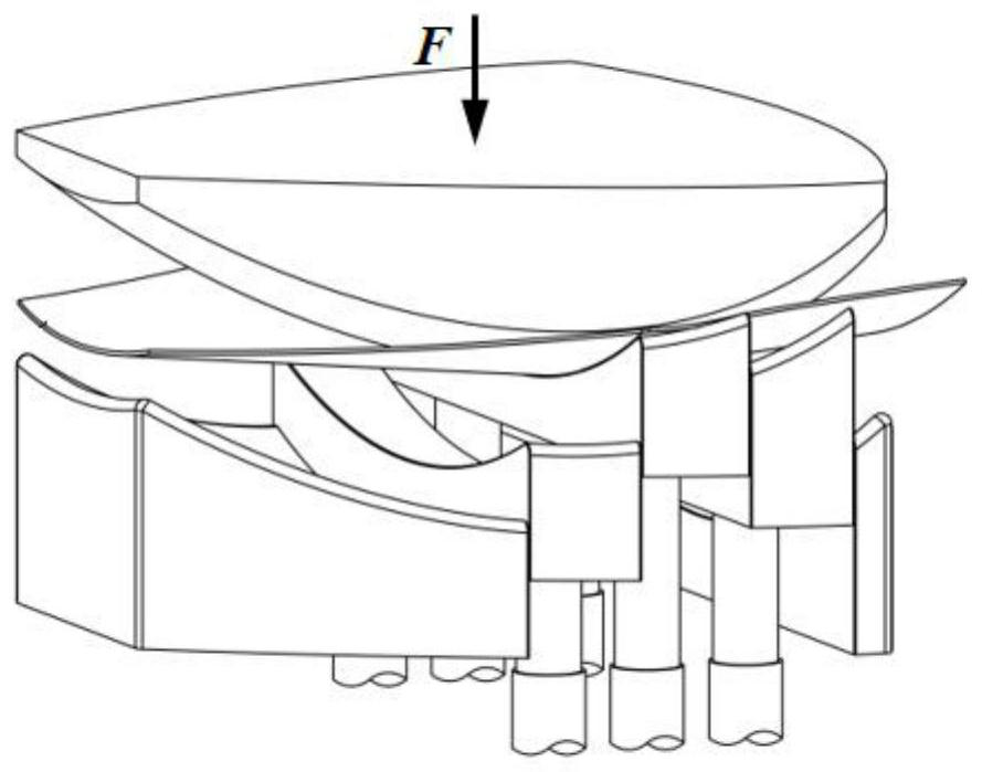
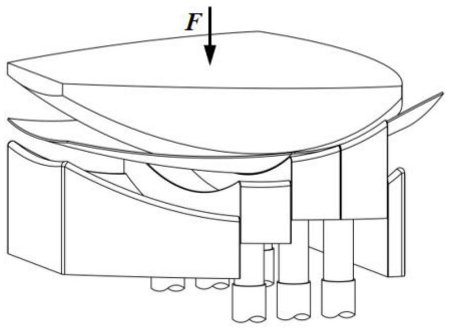
[0045] combine figure 1 , figure 2 , image 3 , Figure 4 , Figure 5 and Figure 6To illustrate, this special example of implementation provides a partition molding method for aluminum alloy curved surface parts. This method decomposes the large deformation of the entire region into small deformations of each partition, reduces the contact area and deformation difference of each partition, and reduces the The tangential compressive stress of each partition, thereby reducing the wrinkling of the formed part. The plate 2 is placed between the upper mold 1 and each partition mold, and the spring 6 is installed at the lower end of each partition mold to realize the elevation. The elevation height of the near big end partition 7 of the die is 50 mm, and the small end partition 3 of the lower die and the large end partition 8 of the lower die are not raised. The upper die 1 is pressed down, so...

Embodiment 2

[0053] Three partitions-30-titanium alloy-forming and quenching integration

[0054] combine Figure 7 To illustrate, this special example of implementation provides a partition molding method for titanium alloy curved surface parts. This method decomposes the large deformation of the entire region into small deformations of each partition, reduces the contact area and deformation difference of each partition, and reduces the The tangential compressive stress of each partition, thereby reducing the wrinkling of the formed part. The plate 2 is placed between the upper mold 1 and each partition mold, and the lower end of the middle partition 5 of the lower mold is equipped with a spring 6 to realize the elevation, and the height of the elevation is 30mm, and the small end partition 3 of the lower mold and the large end partition 8 of the lower mold are not raised. The upper mold 1 presses down, so that the middle area of ​​the plate 2 sticks to the middle section 5 of the lower...

Embodiment 3

[0062] Five divisions-30-70-50-high strength steel-forming and quenching integration

[0063] combine figure 1 , figure 2 , image 3 , Figure 4 , Figure 5 and Figure 6 To illustrate, this special example of implementation provides a method for the divisional compression molding of high-strength steel curved surface parts. This method decomposes the large deformation of the entire area into small deformations of each division, reduces the contact area and deformation difference of each division, and reduces the The tangential compressive stress of each partition, thereby reducing the wrinkling of the formed part. The plate 2 is placed between the upper mold 1 and each partition mold, and the spring 6 is installed at the lower end of each partition mold to realize the elevation. The elevation height of the near big end partition 7 of the die is 50 mm, and the small end partition 3 of the lower die and the large end partition 8 of the lower die are not raised. The uppe...


PUM

PropertyMeasurementUnit
thicknessaaaaaaaaaa
sizeaaaaaaaaaa
thicknessaaaaaaaaaa

Abstract

The invention discloses a partition molding method for light alloy thin-wall curved surface parts, which comprises the following steps: 1) designing a partition mold according to the deformation law of thin-wall curved surface parts, and formulating the number and arrangement of concave die partitions; 2) forming a light alloy plate After heat treatment or cryogenic treatment, it is transferred and positioned to the partition die; 3) The punch moves downward and gradually contacts the partition die, so that the plate is gradually attached to the mold from the middle area to both sides, until a thin-walled curved surface part of the desired shape is formed ; 4) The punch is reset, and the curved surface part is taken out, and the light alloy thin-walled curved surface part is formed by partition molding. The overall large deformation is decomposed into small deformations of each partition through partition sequential forming, which significantly reduces the shape asymmetry of the real-time forming zone and reduces the compressive stress level at the larger end of the radius of gyration; through partition sequential forming, the deformation of each zone of the slab is changed Sequentially, the easily cracked area is formed first, and the wrinkled area is formed later, so as to improve the deformation uniformity of thin-walled curved surface parts.

Description

technical field [0001] The invention relates to the technical field of sheet metal forming, in particular to a partition molding method for light alloy thin-wall curved surface parts. Background technique [0002] As the new generation of carrier equipment has higher and higher requirements for lightweight and high reliability, light alloys such as aluminum alloys and titanium alloys are widely used in the fields of aviation, aerospace and automobiles due to their high specific strength, stiffness and structural properties. in the main structure. Taking launch vehicles as an example, the aluminum alloy main structure accounts for more than 80%. Aerospace components are usually thin-walled and large in size, and the manufacturing route often adopts the method of split forming + assembly welding. For example: the bottom of the carrier rocket fuel storage tank has an opening size greater than 2 meters, even up to 10 meters. Tailored and welded. In order to meet the subseque...

Claims


Application Information

Patent Timeline
Patent Type & Authority Patents(China)
IPC IPC(8): B21D22/02B21D37/16
CPCB21D22/02B21D37/16
Inventor 凡晓波亢鑫何祝斌
Owner DALIAN UNIV OF TECH
Why Eureka
Try Eureka