Switch, particularly power switch

A power switch and switch technology, applied in the field of power switches, can solve problems such as load damage and switch damage

Inactive Publication Date: 2011-10-12
SIEMENS AG
View PDF4 Cites 6 Cited by
  • Summary
  • Abstract
  • Description
  • Claims
  • Application Information

AI Technical Summary

Problems solved by technology

[0004] The disadvantage here is that the contact arm of the phase in which the short-circuit current occurs sometimes springs back into its on position after being deflected upwards into the off position, which can cause damage to the switch itself and even damage to subsequent loads

Method used


Image

  • Switch, particularly power switch
  • Switch, particularly power switch
  • Switch, particularly power switch

Examples


Embodiment Construction

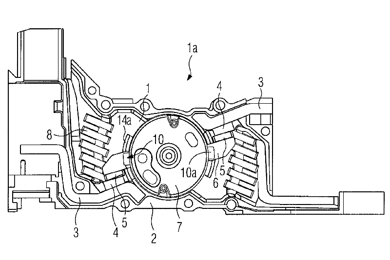
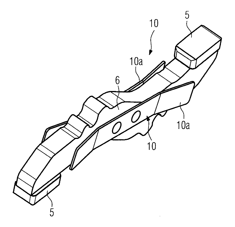
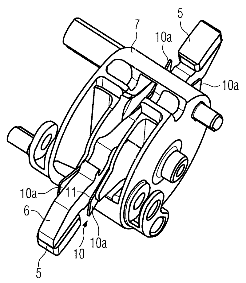
[0018] figure 1 A pole box 1 of a multipole power switch is shown, referred to below as a switch. The pole box 1 forms a housing 1a and consists of two half-shells 2, in figure 1 One of the two half-shells was removed. The pole box 1 has two connection terminals 3 , on the inner ends of which a fixed contact piece 4 is arranged in each case. On the contact piece 4 rests an associated contact piece 5 which is arranged at the free end of a contact arm 6 which is designed here as a double-armed lever. In addition, a rotor 7 in the form of a switching shaft section is rotatably mounted in the pole box 1 , in which rotor the contact arm 6 is in turn mounted in a pivotable manner. The two axes of rotation coincide here. The contact arm 6 can be deflected between an on position and an off position; figure 1 The contact arm 6 is in its on position in which the switch is switched on. When the switch is connected, current flows from the line-side terminal 3 via the two contact pie...


PUM


Abstract

The invention relates to a switch, especially a power switch, which comprises a housing, a rotor rotatably supported in the housing and a contact arm rotatably supported in the rotor. The contact arm can be deflected between an on position and an off position. The free end of the contact arm is equipped with contact members moving along the movement of the contact arm. The contact arm rests on the opposed contact members when the switch is closed and the contact arm is turned on. When a) the current flowing through the contact members exceeds a predetermined value and b) the rotor is rotating, the contact arm is deflected and the abutted contact members are separated from each other. The contact arm is driven to be at the off position by the rotor. In order to ensure the function of the switch, at least one side of the contact arm is equipped with a locking element. The locking element is embedded in the recess of the housing before reaching the off position, so that the contact arm is prevented from rotating back to the on position.

Description

technical field [0001] The invention relates to a switch, in particular a power switch, according to the preamble of claim 1 . Background technique [0002] Power switches are well known and are used to interrupt the current flow in the event of a short circuit. For this purpose, the power switch has a contact arm which can be pivoted between an on position and an off position. The contact arm carries a contact piece at its end, which bears against the opposite contact piece when the switch is closed. The current to be interrupted flows via the switch from the grid-side terminal to the load-side terminal via the two contact pieces and the contact arm. In the event of a short circuit, the contact arms are deflected by the magnetic force generated by the occurring short circuit current, whereby the two contact pieces are separated from each other. The contact arms are mounted rotatably in the rotor; rotation of the rotor likewise leads to a deflection of the contact arms an...

Claims


Application Information

Patent Timeline
Patent Type & Authority Applications(China)
IPC IPC(8): H01H31/04
CPCH01H1/2058H01H71/1009
Inventor A·希尔S·皮克尔T·普尼奥克
Owner SIEMENS AG
Why Eureka
Try Eureka