Washer-drier scrubbing machine

A technology for washing, drying and scrubbing machines, which is applied in the direction of cleaning machinery, cleaning carpets, cleaning floors, etc., and can solve problems such as inaccurate adjustment, changing the effect of detergent, and reducing feed speed

Inactive Publication Date: 2012-07-25
EVOTECH ITAL SRL
View PDF4 Cites 4 Cited by
  • Summary
  • Abstract
  • Description
  • Claims
  • Application Information

AI Technical Summary

Problems solved by technology

Another disadvantage lies in the fact that current washing-drying sweepers exhibit a poor operational flexibility and a poor drying capacity especially and mainly in bends and in crowded or small rooms at the same time. In places and rooms, the operator has to follow a path constrained by the overlap of the cleaning tracks and has to perform wide turning radii to avoid accidents due to the lack of containment systems for spraying the washing mixture and due to the protruding of the tracks due to floor mopping. leaving wet marks, also need to pay attention to the mop protruding transversely to the track in order to avoid collision with possible protruding obstacles
[0008] Another disadvantage lies in the fact that in the presence of waterproof floors with more or less water-absorbing areas, the operator has to manually correct the flow of washing liquid, where cases of inaccurate adjustments are unavoidable, which reflects On the final quality of proper cleaning
[0009] Another drawback that exists in fact is that the current floor mop lowers itself and rubs against the floor in a pivoting manner by means of a lever arm that produces a change in the inclination of the rubber body in the presence of a sag or a hole vibrations, thereby altering its detergent action; moreover, in the presence of areas with large amounts of water, the device has to reduce the feed rate considerably, given the current suction methods with high concavities and restricted air flow in order to allow the treated surface to dry sufficiently

Method used


Image

  • Washer-drier scrubbing machine
  • Washer-drier scrubbing machine

Examples


Embodiment Construction

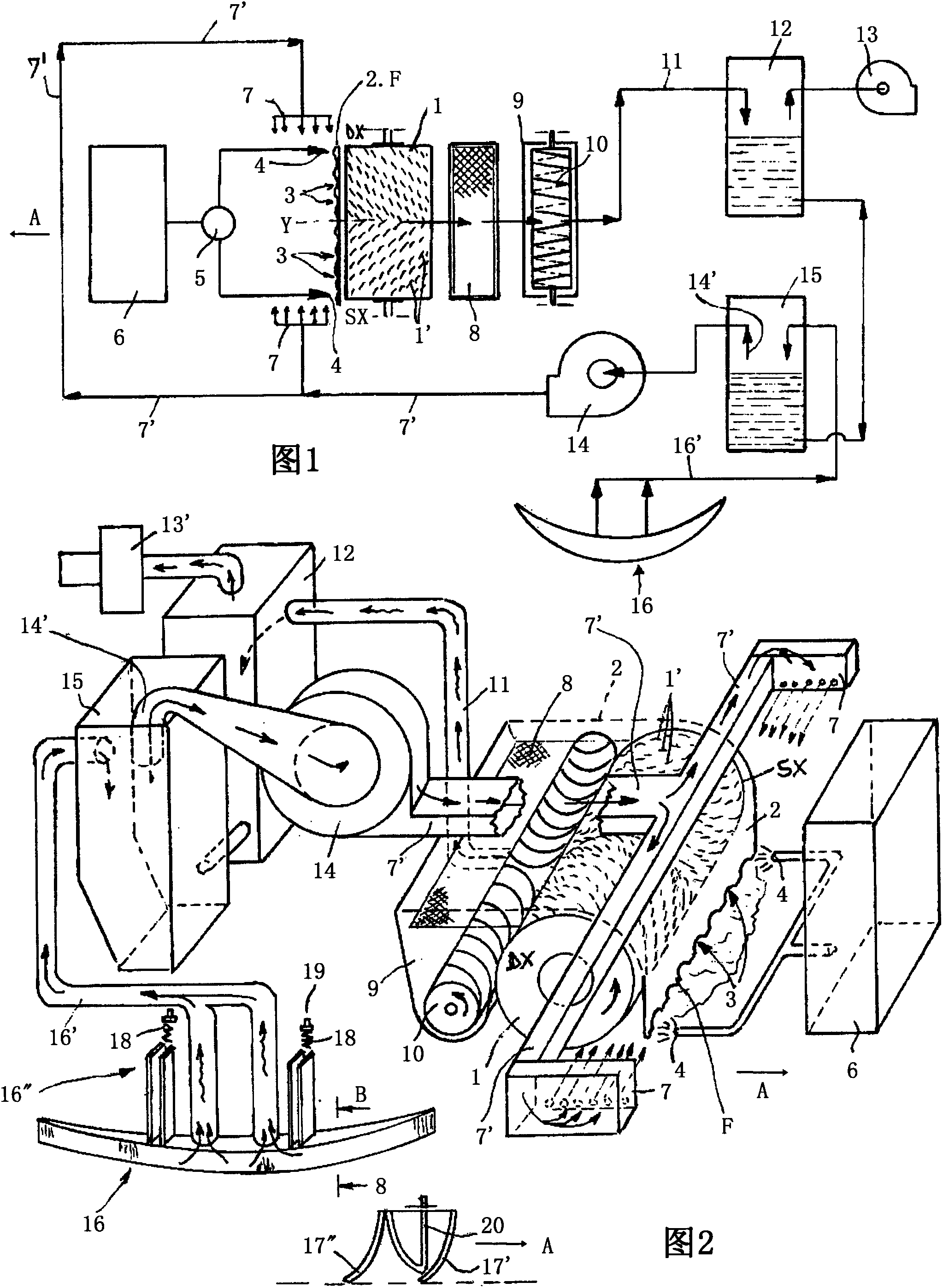
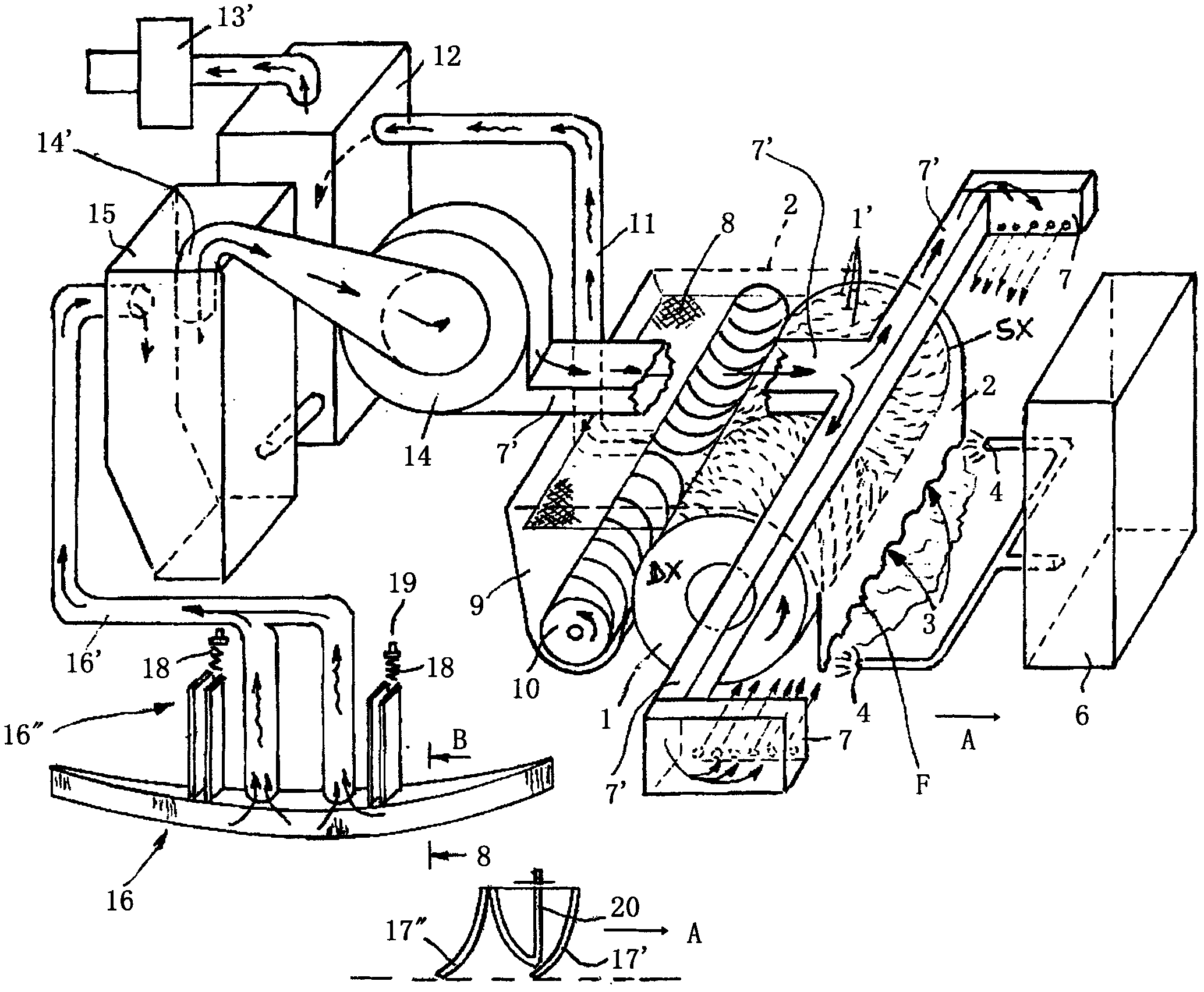
[0024] With reference to the accompanying drawings, according to the invention, a washing-drying scrubbing machine has an accommodating and targeted and guiding orientation system for the front side flow of the wash mixture directed towards the washing trajectory along which said washing-drying scrubbing machine travels, The washing-drying scrubbing machine comprises a structure (2) for accommodating a front side rotating roller brush (1), the outer peripheral surface of which is covered by pointed bristles (1 '), the pointed mane (1') facing upwards and converging from the L and R end edges towards its central axis of symmetry (Y) near the front part of the front rotating roller brush (1) so as to face the operating area, the rotating roller brush (1) is arranged to face The lower part of the structure (2) on which is arranged a flap (F) comprising a number of small aligned openings (3) oriented and facing the floor to be washed.

[0025] On the side of the housing (2) facing...


PUM


Abstract

A washer-drier scrubbing machine comprises a rotating roll brush (1) the surface thereof covered of spiked bristles (1') facing upwards and towards the centre in the proximity of its front portion; it is covered by a structure (2) the lower edge thereof, extended downwards and in the proximity of the ground is provided with a flap (F) comprising some aligned openings (3) oriented and facing the floorings. At the sides of the casing (2) and facing the ground some sprayers (4) fed with water-detergent mixtures pumped from a tank (6) are aligned. In the proximity of the sprayers (4) there are arranged as many diffusers of compressed air (7) which prevents the sprayed washing mixture from expanding outside the outline of said structure (2) and from being conveyed only towards the openings (3) and towards the rotating brush (1), or only, and not beyond, on the track along which the washer-drier scrubbing machine proceeds. The dirty water collected by the roll (1) is sent to a tank (12) through: a separator (8) which retains the high consistency dirt, an intermediate container (9) comprising a bi-helical screw brush (10) converging to the centre and a suction duct (11). The compressed air feeding the diffusers (7) is produced by a fan (14) the suction inlet thereof, arranged inside a tank (15), sucks and collects the dirty water collected by a rear parabolic floor wiper (16).

Description

technical field [0001] The invention relates to a washing-drying scrubbing machine provided with a containment and guidance system on the front side for the flow of washing mixture introduced on its operating trajectory. Background technique [0002] It is known that washing-drying machines currently on the market are basically equipped with a box-type pump assembly for a water-detergent washing mixture that can be dispersed near the washing unit comprising disc-shaped flat brushes, or small-diameter Adjacent to the pair of counter-rotating cylindrical brushes, the box pump assembly is combined with a rear receptacle intended to collect solid objects (eg, debris, etc.). The wash mix from the tank is conveyed near the said rotating brush and the dirty water and small debris is conveyed into the separator container which keeps them falling back to the floor, the muddy water scraped laterally by the curved rubber belt is pivoted The floor mopping is guided and conveyed by the ...

Claims


Application Information

Patent Timeline
Patent Type & Authority Applications(China)
IPC IPC(8): A47L13/26
CPCA47L11/4041A47L11/302A47L11/4044
Inventor 维多利亚·柏图兹
Owner EVOTECH ITAL SRL
Why Eureka
Try Eureka