Drive unit

A technology of drive unit and rotary joint, which is applied in the direction of passing components, rolling contact bearings, and rotating bearings. It can solve the problems of support and shaft clearance, unfavorable consumption of inherent lubricating materials, and increased temperature, and achieve small concentricity deviation. Effect

Inactive Publication Date: 2015-08-26
SMS DEMAG AG
View PDF6 Cites 0 Cited by
  • Summary
  • Abstract
  • Description
  • Claims
  • Application Information

AI Technical Summary

Problems solved by technology

[0006] A disadvantage at this type of solution, as well as at other known solutions, is that there is a play between the bearing and the shaft
Likewise, the bearing's inherent lubricating material consumption is detrimental
Additional disadvantages are the increased temperature of the medium used during operation and sealing problems due to the large gap between the pre-rotating swivel joint part and the stationary swivel joint part

Method used


Image

  • Drive unit
  • Drive unit
  • Drive unit

Examples


Embodiment Construction

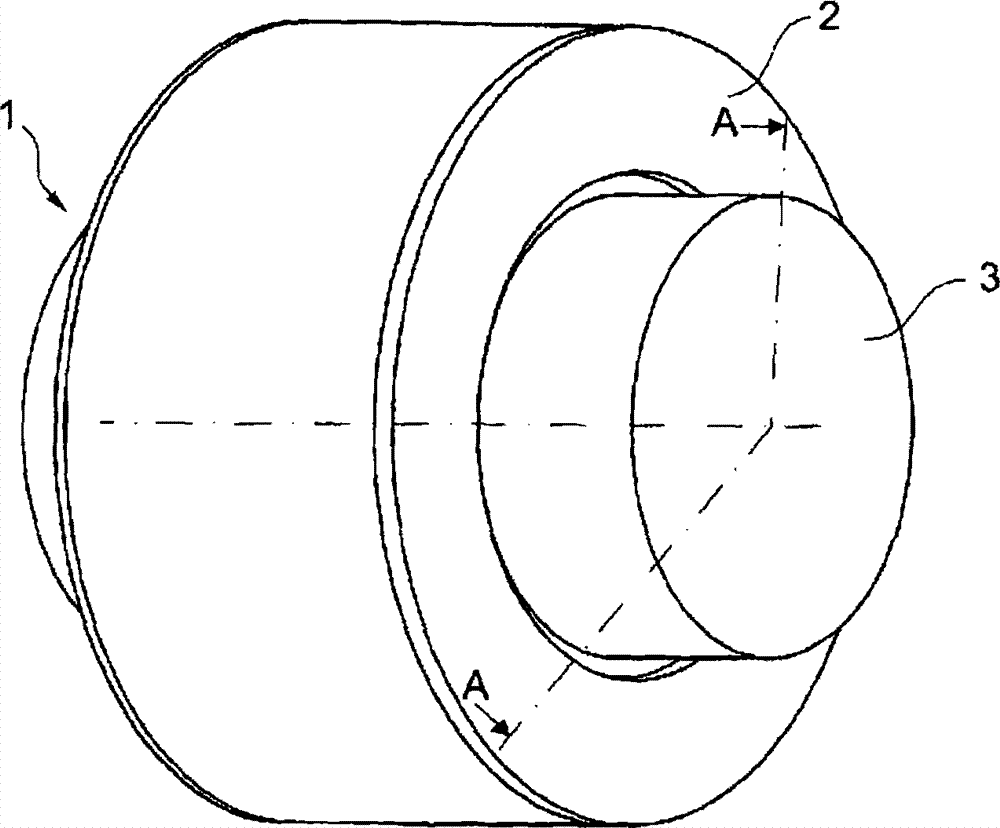
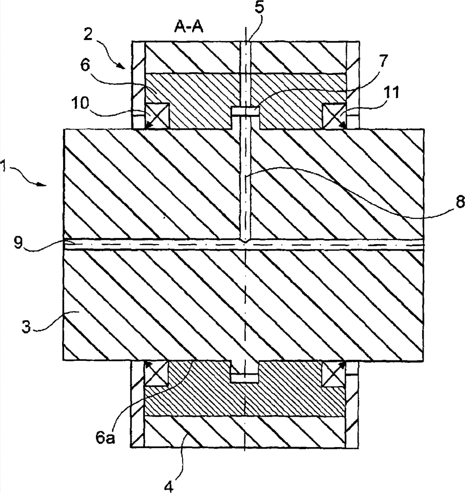
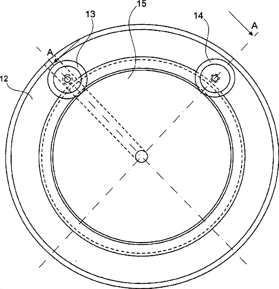
[0031] In the first embodiment of the present invention ( image 3 ,4), the swivel joint has a swivel joint part 12 fixed at the device, which is supported by two pairs of supporting rollers 13, 14 that are mounted on the swivel joint part 12 at the end side to rotate relative to the swivel joint part 15. The two pairs of support rollers 13, 14 are arranged at a suitable angle to each other. The position of the support rollers 13 , 14 relative to the housing part 16 of the swivel joint part 15 is determined via the shaft or via lateral fastening means. Correspondingly, an annular bearing 19 is located between the roller shaft 17 and the housing part 18 .

[0032]The support rollers 13 , 14 lie outside an annular cavity 22 which surrounds the swivel joint part 15 , which is sealed by seals 20 , 21 . A medium supply line 23 leading to the cavity 22 is installed in the housing part 16 . From there, the medium for lubrication and / or cooling is conveyed into radially extending c...


PUM


Abstract

The invention relates to a rotary union for supplying and / or discharging a medium under pressure into or out of an axial cavity of a rotating machine part, comprising a union part (12), which does not rotate and is fixed relative to the device, a rotary union part (15) and with bearing means as well as sealing components, which act in a radial sealing plane between the rotary union part (15) and the union part (12) fixed relative to the device. The rotary union is characterized in that the bearing means comprise individual step bearings (13, 14), which fix the radial distance between the union part (12) fixed relative to the device and the rotary union part (15).

Description

technical field [0001] The invention relates to a swivel joint (Drehdurchführung) for feeding and / or discharging a pressurized medium into and / or out of an axial cavity of a rotating mechanical part, the swivel joint having a non-rotating A joint part, a rotating joint part with a bearing means and a sealing means which acts in a radial sealing plane between the rotating joint part and the joint part fixed on the device. Background technique [0002] A swivel joint generally includes a non-rotating joint part fixed at the device and a joint part rotating together with a rotating mechanical part, wherein a sealing device is arranged between the joint part fixed at the device and the rotating joint part. Such swivel joints are used to supply coolant to rolls or rollers, which are to some extent shafts or axles supported at their ends by bearings. Under heavier loads, these rotating mechanical parts suffer from a certain deflection of the shaft, which causes a so-called angula...

Claims


Application Information

Patent Timeline
Patent Type & Authority Patents(China)
IPC IPC(8): F16L27/087F16C19/50
CPCF16C19/50F16L27/087F16L27/08
Inventor R·格里梅尔C·孙德曼U·伯克霍尔茨
Owner SMS DEMAG AG
Why Eureka
Try Eureka