Air purifying device

An air cleaning device and air cleaning technology, which can be used in air humidification systems, air quality improvement, air conditioning systems, etc., and can solve problems such as poor use feeling.

Active Publication Date: 2011-10-12
PANASONIC CORP
View PDF1 Cites 6 Cited by
  • Summary
  • Abstract
  • Description
  • Claims
  • Application Information

AI Technical Summary

Problems solved by technology

However, there are cases where it is difficult to visually confirm the operation display lamp in a place far from the air cleaning device, so there is a problem of poor usability.

Method used


Image

  • Air purifying device
  • Air purifying device
  • Air purifying device

Examples


Embodiment approach 1

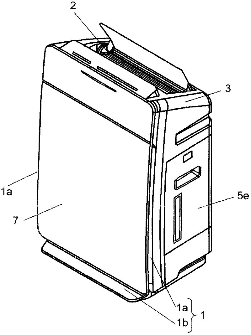
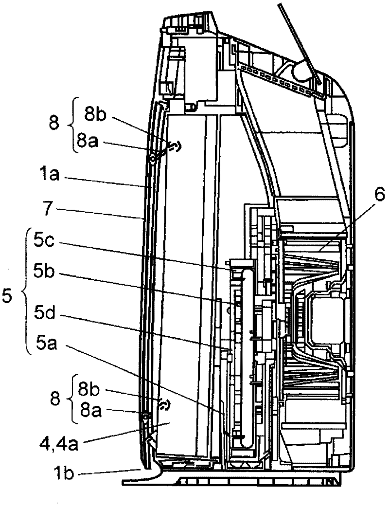
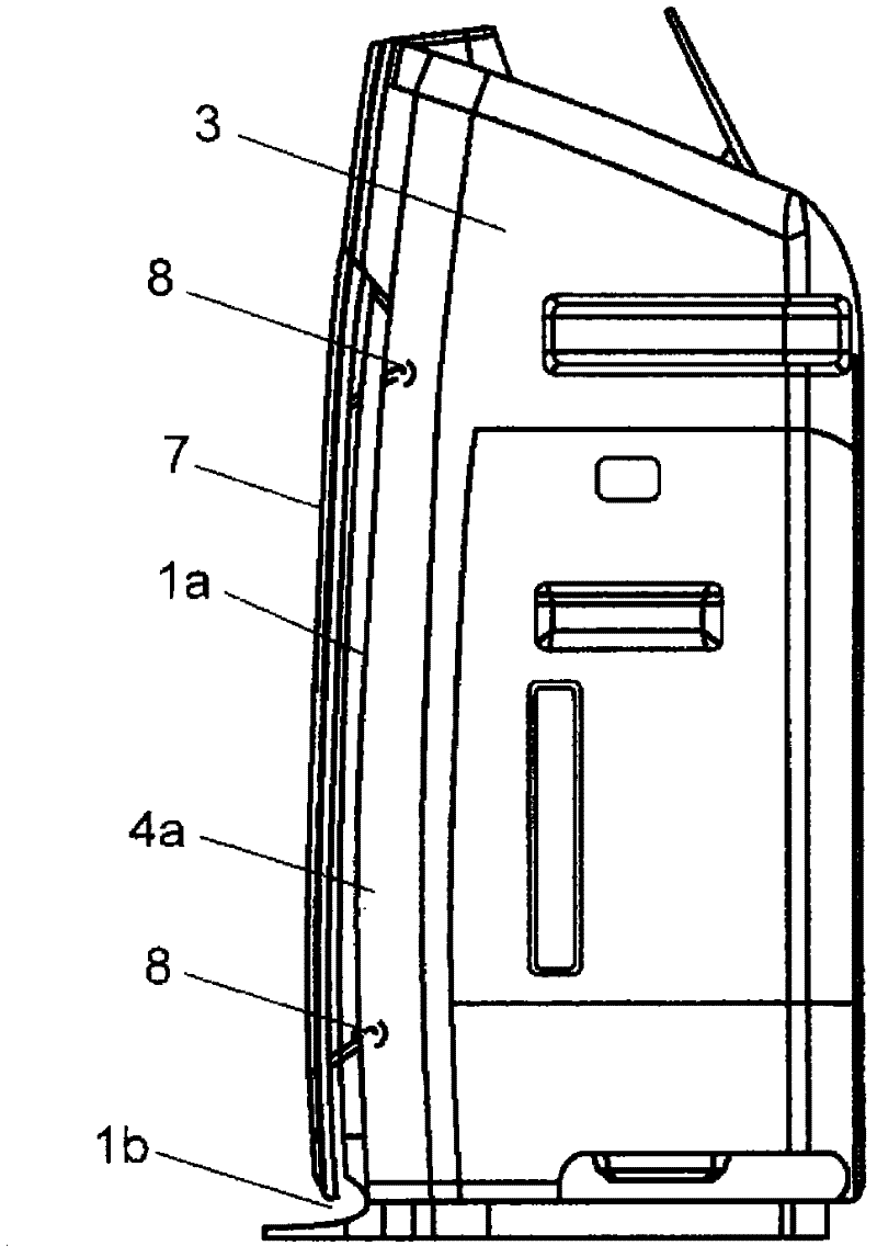
[0030] figure 1 It is a schematic diagram of the air cleaning device according to Embodiment 1 of the present invention, figure 2 is a schematic sectional view of the air cleaning device. The air cleaner according to Embodiment 1 of the present invention includes a main body casing 3 , an air cleaner 4 , a humidifier 5 , and a blower 6 . Here, the main body casing 3 has an intake port 1 and an exhaust port 2 . The air cleaning unit 4 is provided in the main body casing 3 . The air blower 6 sucks indoor air from the air inlet 1 into the main body casing 3 via the air cleaner 4 , and is provided on the air path from the air inlet 1 to the air outlet 2 . In addition, a front surface decorative panel 7 is provided on the front surface of the main body casing 3 . The humidifier 5 is provided on the downstream side of the air cleaner 4 on the wind path.

[0031] The intake port 1 includes a first intake port 1 a provided on both side surfaces of the main body case 3 and a seco...

Embodiment approach 2

[0066] Figure 7 It is a perspective view of an air cleaning device according to Embodiment 2 of the present invention, Figure 8 is a cross-sectional view in the case where the front surface decorative panel of the air cleaning device is located at the middle point, Figure 9 is a cross-sectional view of the air cleaning device when the front surface decorative panel is located at the uppermost point, Figure 10 It is a cross-sectional view in the case where the front decorative panel of the air cleaner is located at the lowest point.

[0067] The air cleaning device according to Embodiment 2 of the present invention includes: a main body casing 103 having an air inlet 101 and an exhaust port 102, an air cleaning unit provided in the main body casing 103, a humidifier and a blower on the downstream side of the air cleaning unit. Section 112.

[0068]The blower unit 112 sucks indoor air from the air inlet 101 through the air cleaning unit into the main body casing 103 , and...

Embodiment approach 3

[0100] Figure 11 It is a perspective view of an air cleaning device according to Embodiment 3 of the present invention, Figure 12 is a sectional view of the air cleaning device, Figure 13 is a front view of the humidifying part of the air cleaning device, Figure 14 It is a sectional view of the humidifying part of this air cleaner.

[0101] The air cleaner according to Embodiment 3 of the present invention includes a vertically long box-shaped main body casing 203 having an air inlet 201 and an exhaust port 202 , and an air cleaning unit and a humidifying unit provided in the main body casing 203 . A suction port 201 is provided on a side surface of the main body casing 203 , and an exhaust port 202 is provided on a top surface of the main body casing 203 .

[0102] The air cleaning unit is an air cleaning filter 205 in which a pleated filter material is fixed to a frame like a picture frame, and is provided near the air inlet 201 . The air sucked in from the suction p...


PUM


Abstract

An air purifying device provided with: a body case having an air suction opening and an air discharge opening; an air purifying section provided in the body case; and an air sending section provided in an airflow path for sucking indoor air into the body case from the air suction opening through the air purifying section and discharging the air indoors from the air discharge opening. The air suction opening is constructed from a first air suction opening provided in at least one side face of the body case, and also from a second air suction opening provided in the lower part of the front face of the body case. A front decorative plate is provided to the front face of the body case, and, out of the area of opening of the first and second air suction openings, the area of opening of at least the second air suction opening can be changed by moving up and down the front decorative plate.

Description

technical field [0001] The present invention relates to air cleaning devices. Background technique [0002] Conventional air cleaners have the following configurations. [0003] That is, it is configured to include: a main body casing having an air intake port and an exhaust port; an air cleaning mechanism provided in the main body casing; The wind path that goes into the main body casing and exhausts from the exhaust port to the room. The prior art document of this air cleaner is described in the following patent document 1. [0004] In the conventional air cleaner, it is possible to confirm the operation status, that is, whether the operation gear is weak operation or strong operation, through the operation display lamp displayed on the main body operation panel, or the like. However, it may be difficult to visually confirm the operation display lamp at a place far from the air cleaning device, so there is a problem of poor usability. [0005] [Patent Document 1] Japan...

Claims


Application Information

Patent Timeline
IPC IPC(8): F24F6/00B01D46/00F04D29/44F24F6/06F24F7/00F24F8/117F24F8/125
CPCF24F6/06Y02A50/20F24F8/117F24F8/10F24F8/125
Inventor 野津仁志石黑真衣森丰木下刚
Owner PANASONIC CORP
Why Eureka
Try Eureka