

Carbon tank for adsorbing fuel vapor
A carbon canister and fuel technology, which is used in the collection/return of condensed fuel, adding non-fuel substances to fuel, engine components, etc., can solve the problems of limited desorption conditions, fatigue damage of diaphragms, and reduced anti-aging ability, etc. Achieve the effect of cost reduction, system structure simplification and reliability improvement
- Summary
- Abstract
- Description
- Claims
- Application Information
AI Technical Summary
Problems solved by technology
Method used
Image

Examples
Embodiment 1
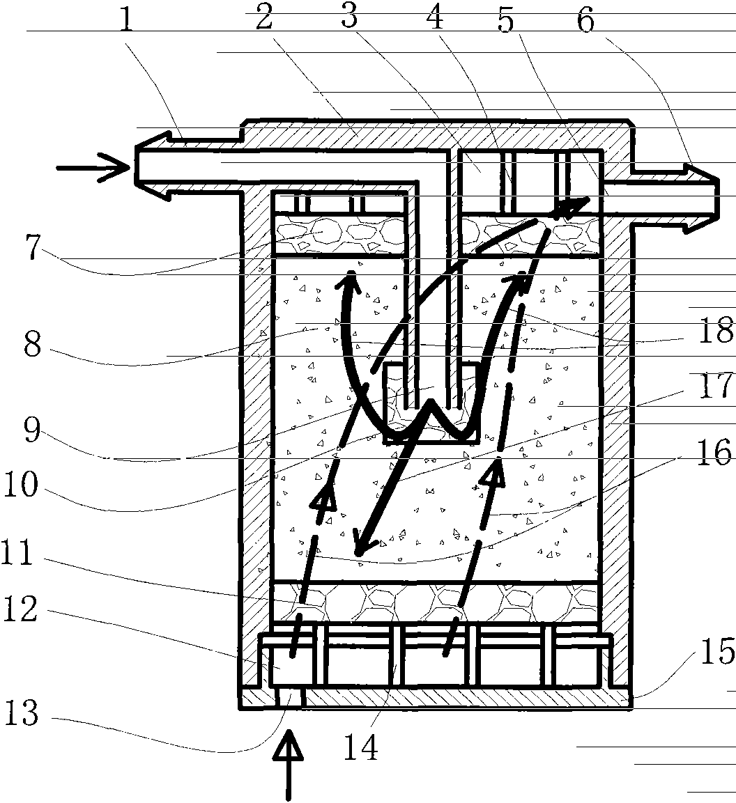
[0024] Such as figure 1 Shown is a cross-sectional view of the first embodiment provided by the present invention. The main components of the carbon tank include: adsorption nozzle 1, shell 2, first cavity 3, first support column 4, desorption port 5, desorption nozzle 6, first carbon isolation net 7, activated carbon 8, adsorption Port 9, third carbon isolation net 10, second carbon isolation net 11, second cavity 12, air vent 13, second support column 14, end cap 15. The adsorption nozzle 1 and the desorption nozzle are arranged on the housing 2 , and the gas vent 13 is arranged on the end cover 15 . The first carbon isolation net 7, the second carbon isolation net 11 and the housing 2 form a carbon chamber for storing activated carbon 8, and the adsorption port 9 extends into the inside of the carbon chamber, and its end is covered with a third carbon isolation net 10 , to prevent activated carbon 8 from entering the adsorption port 9. The first support column 4 supports...
Embodiment 2
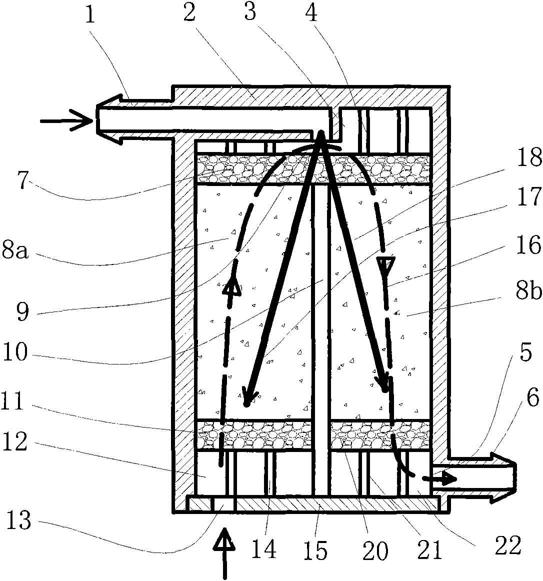
[0029] Such as figure 2 Shown is a sectional view of the second embodiment provided by the present invention, which is a better solution than the first embodiment. and figure 1 Parts with the same name in the above use the same label, and the characteristics that are different from Example 1 are mainly: the carbon chamber is divided into left and right parts by a partition 10, the left carbon chamber stores activated carbon 8a, and the right carbon chamber stores activated carbon 8b. The port 9 leads to the middle of the first cavity 3, the desorption nozzle 6 is located at the lower right part of the housing 2, the lower end of the activated carbon 8b on the right is carried by the fourth carbon isolation net 20, and the third support column 21 supports the fourth carbon isolation The net 20 forms a third cavity 22 , and the desorption port 5 is located on the wall of the third cavity 22 .
[0030] figure 2 The working process of the shown carbon canister of the present ...
Embodiment 3
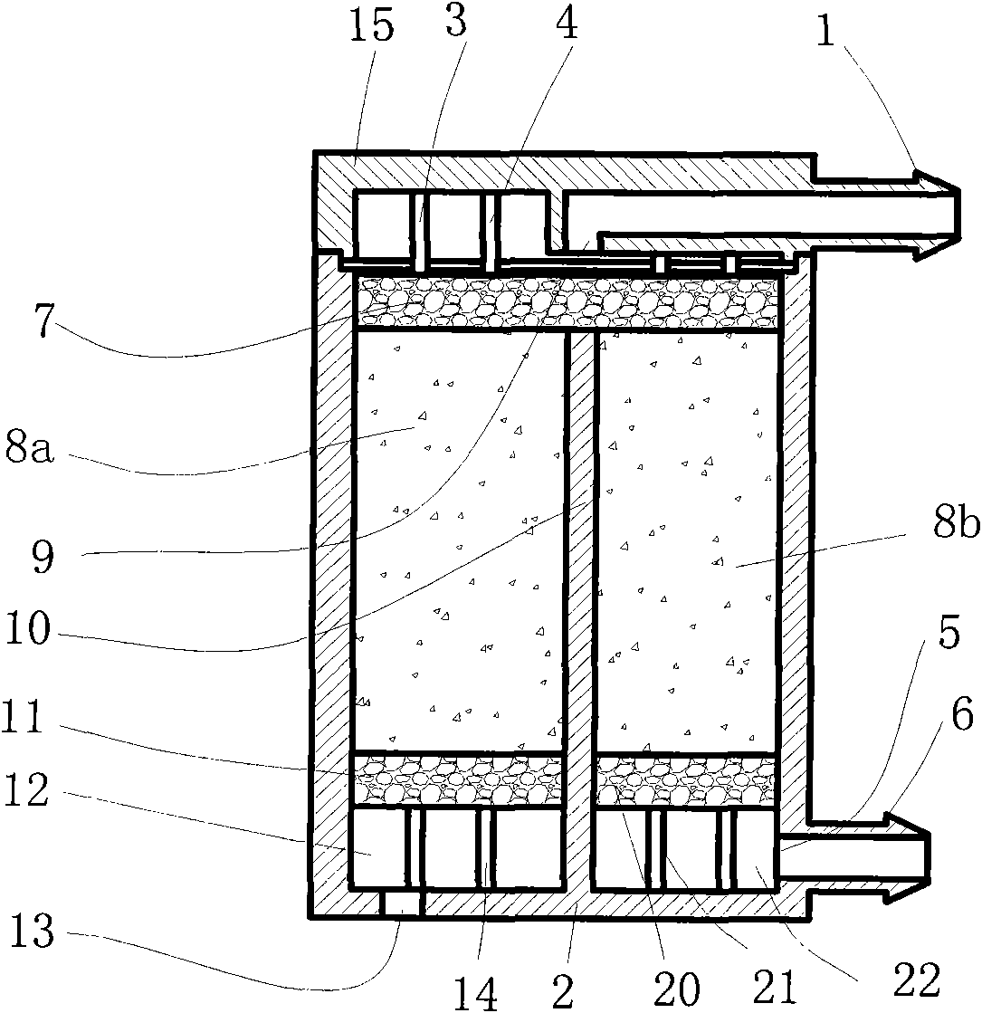
[0035] image 3 The sectional view showing the third embodiment provided by the present invention is a further optimization of the second embodiment. and figure 1 with figure 2 Components with the same names in the above use the same labels, and the main features that are different from Embodiment 2 are: the housing 2 is placed on the lower part, the end cover 15 is placed on the upper part, the adsorption nozzle 1 is set on the end cover 15, and the detachment nozzle 6 and the air vent 13 are arranged on the housing 2, and the partition 10 and the housing 2 are integrally injection-molded, so the structure is more compact, and the partition 10 is easy to completely isolate the activated carbon 8a on the left and the activated carbon 8b on the right, completely eliminating In order to ensure that the desorption air flow is directly short-circuited from the second cavity 12 to the third cavity 22, it is easy to ensure the desorption efficiency.
[0036] Figure 4 For an ex...
PUM
 Abstract
Description
Claims
Application Information