Electromagnetic speed-regulation driving system

A drive system, electromagnetic speed regulation technology, applied in the direction of control system, electromechanical transmission device, electrical components, etc., can solve the problems of increased design cost, complex design, inevitable permanent magnet demagnetization, etc., to reduce loop reluctance, The effect of reducing the inter-axis error and simplifying the system structure

Inactive Publication Date: 2011-10-19
NORTHEASTERN UNIV LIAONING
View PDF2 Cites 5 Cited by
  • Summary
  • Abstract
  • Description
  • Claims
  • Application Information

AI Technical Summary

Problems solved by technology

This kind of permanent magnet speed control system uses permanent magnets to realize the demagnetization phenomenon of permanent magnets that is inevitable for speed control; in order to achieve speed control, a set of air gap adjustment devices must be equipped, and the design is more complicated
In the case of automatic speed regulation, it is also necessary to increase the servo system, which greatly increases the design cost

Method used


Image

  • Electromagnetic speed-regulation driving system
  • Electromagnetic speed-regulation driving system
  • Electromagnetic speed-regulation driving system

Examples


Embodiment 1

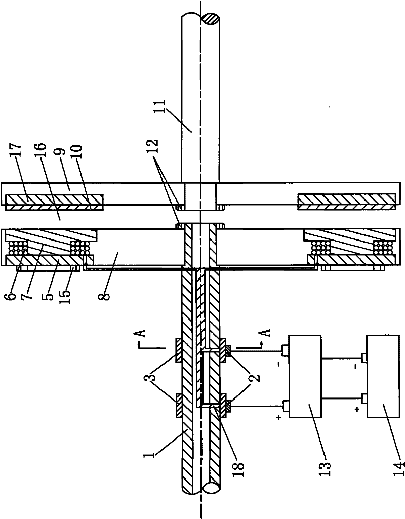
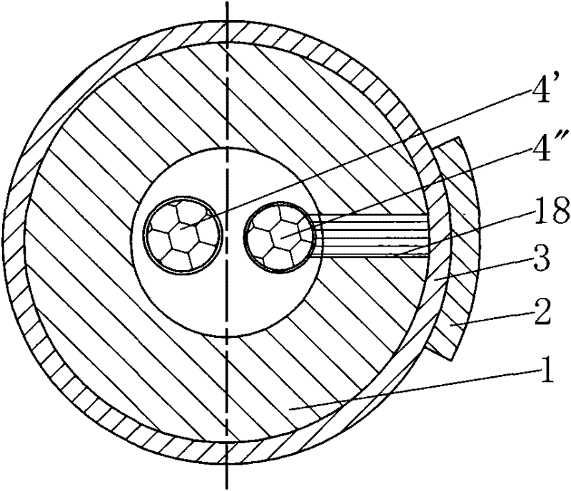
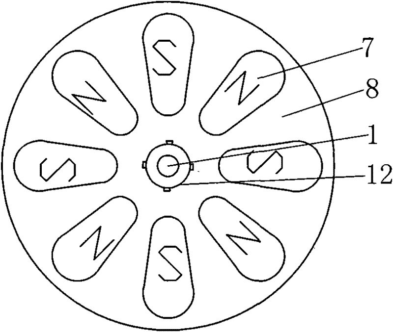
[0018] Embodiment 1: as figure 1 As shown, the present invention includes an input shaft 1 and an output shaft 11 arranged concentrically, an electric slip ring 3 sleeved on the input shaft 1, two brushes 2 close to the electric slip ring 3, and an electromagnetic rotor installed at the end of the input shaft 1 8. The conductor rotor 9, the current controller 13, and the power supply 14 installed on the end of the output shaft 11, the electromagnetic rotor 8 is installed with the iron core 7 around the coil 6 along the circumference, and the coil 6 and the two electric slip rings 3 respectively pass through the wire 4' , 4" connection, the two brushes 2 on the two electric slip rings 3 are connected to the positive and negative poles of the power supply 14 through the current controller 13, the conductive ring 10 is provided on the conductor rotor 9, and the end faces of the conductive ring 10 and the electromagnetic rotor The end faces of the iron core 7 of 8 are arranged cor...


PUM


Abstract

The invention provides an electromagnetic speed-regulation driving system, belonging to the technical field of speed-regulation driving systems. The electromagnetic speed-regulation driving system comprises an input shaft and an output shaft that are concentrically arranged, two electric slip rings sheathed on the input shaft, two electric brushes arranged on the electric slip rings, an electromagnetic rotor arranged at the input shaft end, a conductor rotor arranged at the output shaft end, a current controller and a power supply, wherein iron cores twisted by coils are arranged on the electromagnetic rotor along the circumference; the coils are connected with the two electric slip rings respectively; the two electric brushes are connected with the power supply by the current controller; the conductor rotor is provided with a conductive ring; the end surface of the conductive ring is arranged opposite to the end surfaces of the iron cores of the electromagnetic rotor and an air clearance is formed between the two end surfaces. In the invention, as the relative position relationship of the input shaft and the output shaft is fixed unchangeably, the relative surfaces of the conductor rotor and the electromagnetic rotor are spaced by a fixed air clearance; the conductor rotor and the electromagnetic rotor are coupled with each other by a magnetic field that is generated by controlling the coil currents; and the intensity of the magnetic field generated by the electromagnet can be changed by the current controller, thus changing the torque and the rotating speed, and achieving the aim of regulating speed.

Description

technical field [0001] The invention belongs to the technical field of speed-regulating drive systems, in particular to an electromagnetic speed-regulating drive system. Background technique [0002] With the development of modern technology, the requirements for the production environment such as noise, dust, sealing, cleaning, etc. are getting higher and higher. Traditional rigid couplings can no longer meet the needs of future technology due to the noise and friction generated by the direct rigid connection and the need for lubrication. To meet the needs of development, it is replaced by a magnetic coupling structure, so the magnetic coupler came into being. Most of the existing magnetic coupler speed control systems use permanent magnets to generate a magnetic field. The magnetic field passes through the air gap to couple the master-slave and the moving shaft together, and adjusts the size of the coupled magnetic field by adjusting the air gap to achieve speed control. ...

Claims


Application Information

Patent Timeline
Patent Type & Authority Applications(China)
IPC IPC(8): H02P17/00
Inventor 满永奎边春元王双全
Owner NORTHEASTERN UNIV LIAONING
Why Eureka
Try Eureka