
Glow plug and method for producing the same

A technology for glow plugs and power supply lines, applied in combustion methods, lighting and heating equipment, combustion ignition, etc., can solve the problems of indirect loss, breakage, etc., and achieve the effect of reducing the risk of damage, simple design, and high-quality brazing connection

Active Publication Date: 2013-10-16
BORGWARNER BERU SYST
View PDF10 Cites 0 Cited by
  • Summary
  • Abstract
  • Description
  • Claims
  • Application Information

AI Technical Summary

Problems solved by technology

[0002] This type of glow plug has the disadvantage that the tip of the ceramic heater, also called a glow pencil, breaks off during operation and leads to serious consequential losses

Method used


Image

  • Glow plug and method for producing the same
  • Glow plug and method for producing the same
  • Glow plug and method for producing the same

Examples


Embodiment Construction

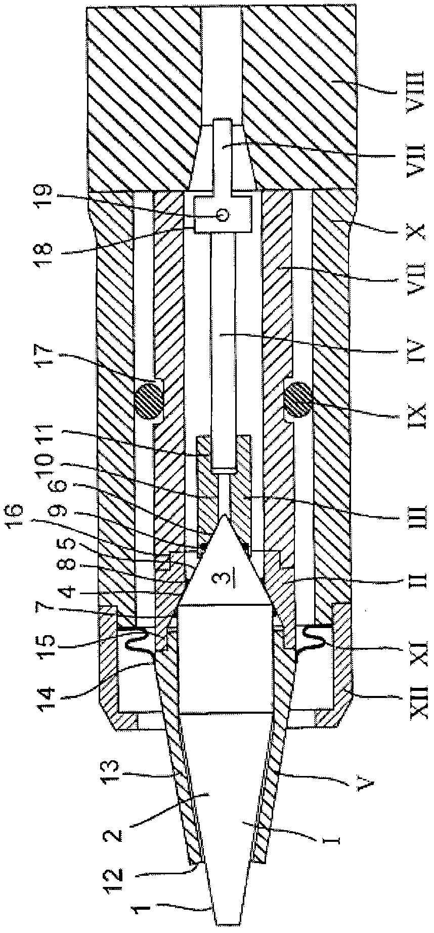
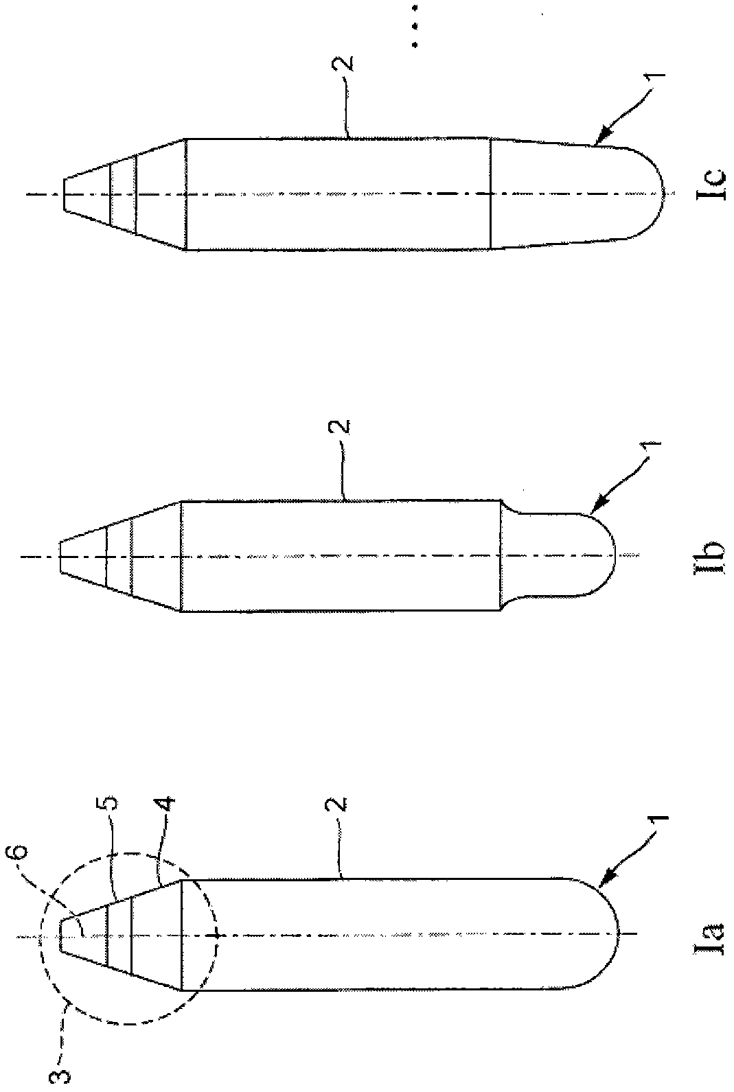
[0069] figure 1 An exemplary embodiment of a glow plug according to the invention is shown with a ceramic glow pin I protruding from a housing consisting of an upper housing part X and a lower housing part X and surrounded by a sleeve V Part XII Composition. The heating pencil 1 has an inner conductor, an outer conductor and an insulator arranged between them. The glow pencil tapers toward its end, which is arranged in the housing, preferably conically. For electrical connection to the inner conductor of the glow pencil, this end is inserted into an inner rod contact III which is connected to the supply line IV and to which the glow pencil I is soldered.

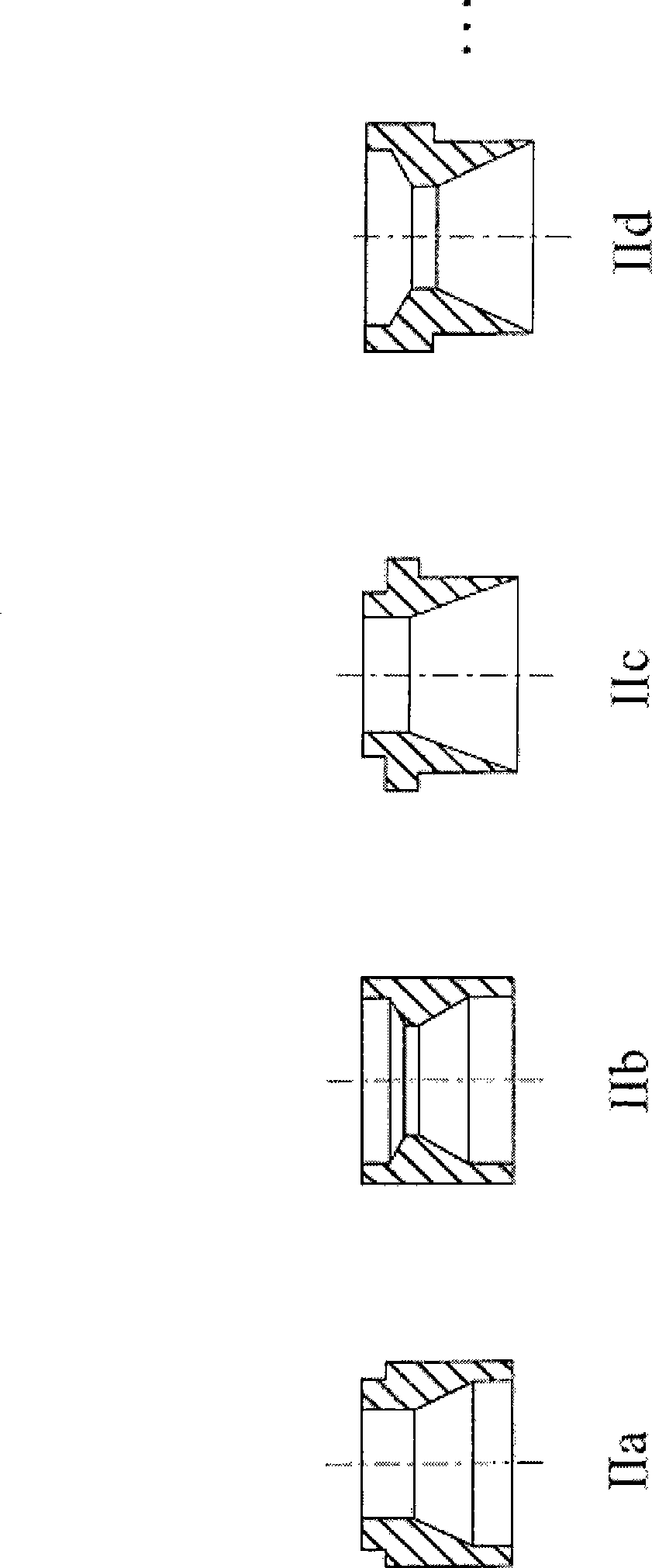
[0070] The outer conductor of the glow pencil is electrically connected via the contact element II, which is formed as a ring in the exemplary embodiment shown. The contact ring II is soldered to the glow pencil I, has a narrowed portion (which in the exemplary embodiment shown has a conical inner surface) and comprises a...


PUM


Abstract

The invention relates to a glow plug comprising a housing, a ceramic pencil-type glow element which projects from the housing with a first end and is arranged inside the housing with a second end, a feed line which is arranged in the housing and leads to the pencil-type glow element, and a sleeve-type element which surrounds a section of the pencil-type glow element projecting from the housing. The invention is characterized in that the pencil-type glow element has a section surrounded by the housing which section tapers towards the second end, the pencil-type glow element is encircled by a contact element in the housing, which contact element has a section that narrows towards the second end of the pencil-type glow element, said narrowing section encircling at least a subsection of the tapered section of the pencil-type glow element. The invention further relates to a method for producing said glow plug.

Description

technical field [0001] The invention relates to a glow plug, which has a housing, a first end protruding from the housing and a ceramic heating pencil whose second end is arranged in the housing, arranged in the housing and leading to a heat-generating The power supply line of the pen, and the sleeve that wraps the part protruding from the casing of the heating pen. Such glow plugs are known, for example, from documents DE102004055218A1, EP1239222B1 and JP2002243150A. Background technique [0002] Such glow plugs have the disadvantage that the tip of the ceramic heater, also known as a glow pencil, breaks off during operation and causes serious consequential damage. Contents of the invention [0003] The object of the present invention is to provide a method how to reduce this risk of fracture. [0004] This problem is solved by a glow plug in the form of a housing with a first end protruding from the housing and a ceramic glow pencil whose second end is arranged in the ...

Claims


Application Information

Patent Timeline
IPC IPC(8): F23Q7/00
CPCF23Q7/001F23Q2007/004
Inventor 雷纳·海因马丁·阿盖尔
Owner BORGWARNER BERU SYST
Learn More